Tips
Using the Independently Floating Isolated Inputs
6
83
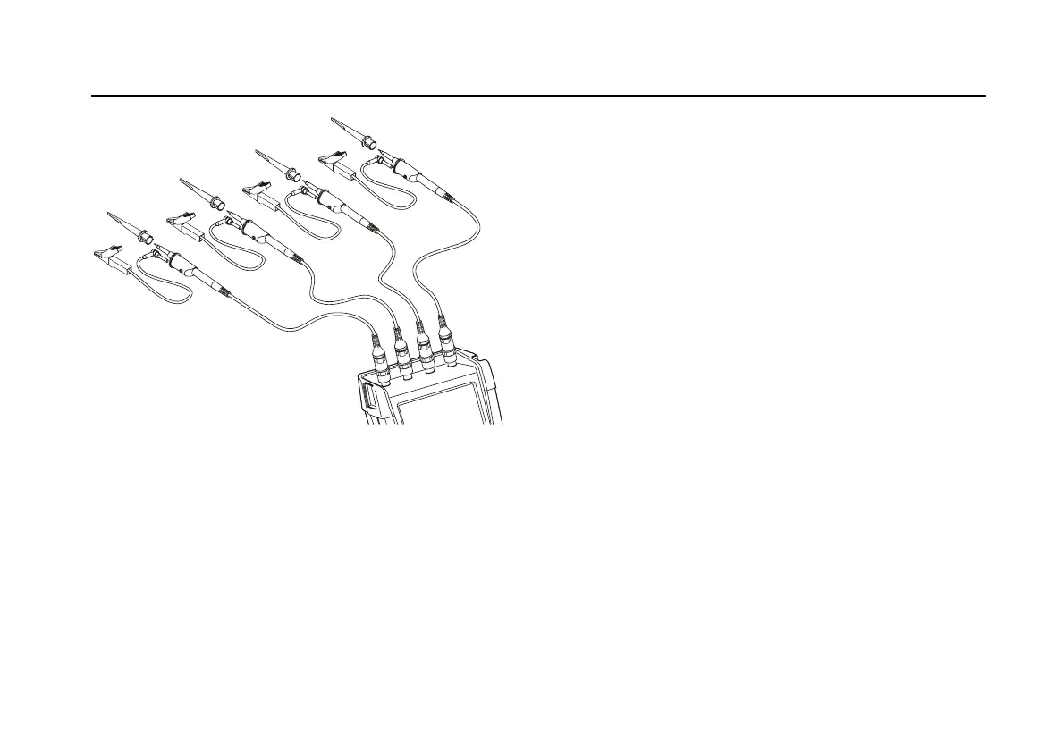
Figure 39. Electronic Connections for Measurements
Using Hook Clips and Alligator Clip Grounding
Warning
To avoid electrical shock, re-apply the
insulation sleeve (Fig. 1 item e)) over the
probe tip when the hook clip is not used. This
also avoids the risk of accidently
interconnecting the reference contact of
multiple probes when groundleads are
connected.
Using the Independently Floating
Isolated Inputs
You can use the independently floating isolated inputs to
measure signals that are independently floating from each
other.
Independently floating isolated inputs offer additional
safety and measurement capabilities compared to inputs
with common references or grounds.
Measuring Using Independently Floating Isolated
Inputs
The test tool has independently floating isolated inputs.
Each input section (A, B, C, D – A, B, METER INPUT) has
its own signal input and its own reference input. The
reference input of each input section is electrically isolated
from the reference inputs of the other input sections. The
isolated input architecture makes the test tool about as
versatile as having four independent instruments. The
advantages of having independently floating isolated
inputs are:
• It allows simultaneous measurement of independently
floating signals.

 Loading...