OPERATION
FRONT
PANEL FEATURES
ITEM NO.
1
Table
2-1.
8010A/8012A Controls, Indicators,
and
Connectors
NAME
FUNCTION
Display
3V2-digit
LCD
display.
Indicates measured input values
and an
overrange condition.
(Also contains an
annunciator
for
low
battery charge,
if the Rechargeable
Battery
Option
is
installed.)
AC/DC Function
Switch
A two-position switch (push IN and push OUT) used to
select
ac (IN) or dc (OUT) for current or voltage
measurement.
V/mA/kn/S
Function Switches
Interlocked switches,
used
with the
AC/DC
Function switch to
select the measurement functions. Pushing one
switch
will
release
the
others.
The
conductance function is
selected by
pushing the kQ switch and one of three
pairs of
Range Function
switches. The Low Ohms feature of the 801 2A is selected by
pressing the
V
and
mA
switches simultaneously.
Range
Switches
Interlocked
switches that select the measurement ranges.
Pushing a
switch
selects the corresponding range and
releases
a depressed switch(es).
mA
Input Connector
A
fuse protected,
test lead connector for current
measurements,
less than 2A.
Fuse
is
accessible from
the front
panel.
COMMON
Input
Connector
Test lead connector used as the low or common input
for
all
measurement functions.
V/kn/S Input
Connector
Test lead connector used as the high input forail voltage, resist-
ance,
continuity
and
conductance
measurement
functions.
10A
Input
Connector
Test
lead connector
used
for the
10A Range current
function of
the 8010A.
Low Ohms
Input
Connector
/ZERO Control
Test lead connector used for the Low Ohms resistance
function
of the
801
2A. ZERO
Control
used to compensate for test
lead
resistance.
POWER Switch
Push-on/push-off switch. Used for energizing
and
de-energiz-
ing
the
instrument.
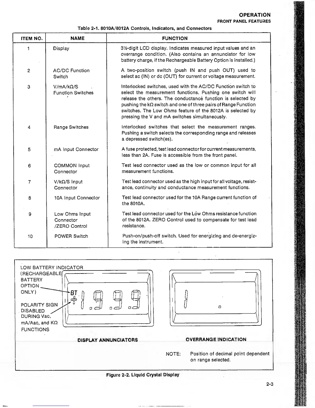
LOW BATTERY IN DICATOR
(
RECHARGEABLEf r
^
BATTERY
\
OPTION.^
f
ONLY)
f
POLARITY SIGN
°
L
DISABLED
DURING
Vac,
^
mA/Aac, and
KQ
[
^
FUNCTIONS
Q Q
,3
.3
DISPLAY
ANNUNCIATORS
OVERRANGE INDICATION
NOTE:
Position of
decimal point dependent
on
range selected.
Figure
2-2.
Liquid
Crystal
Display
2-3