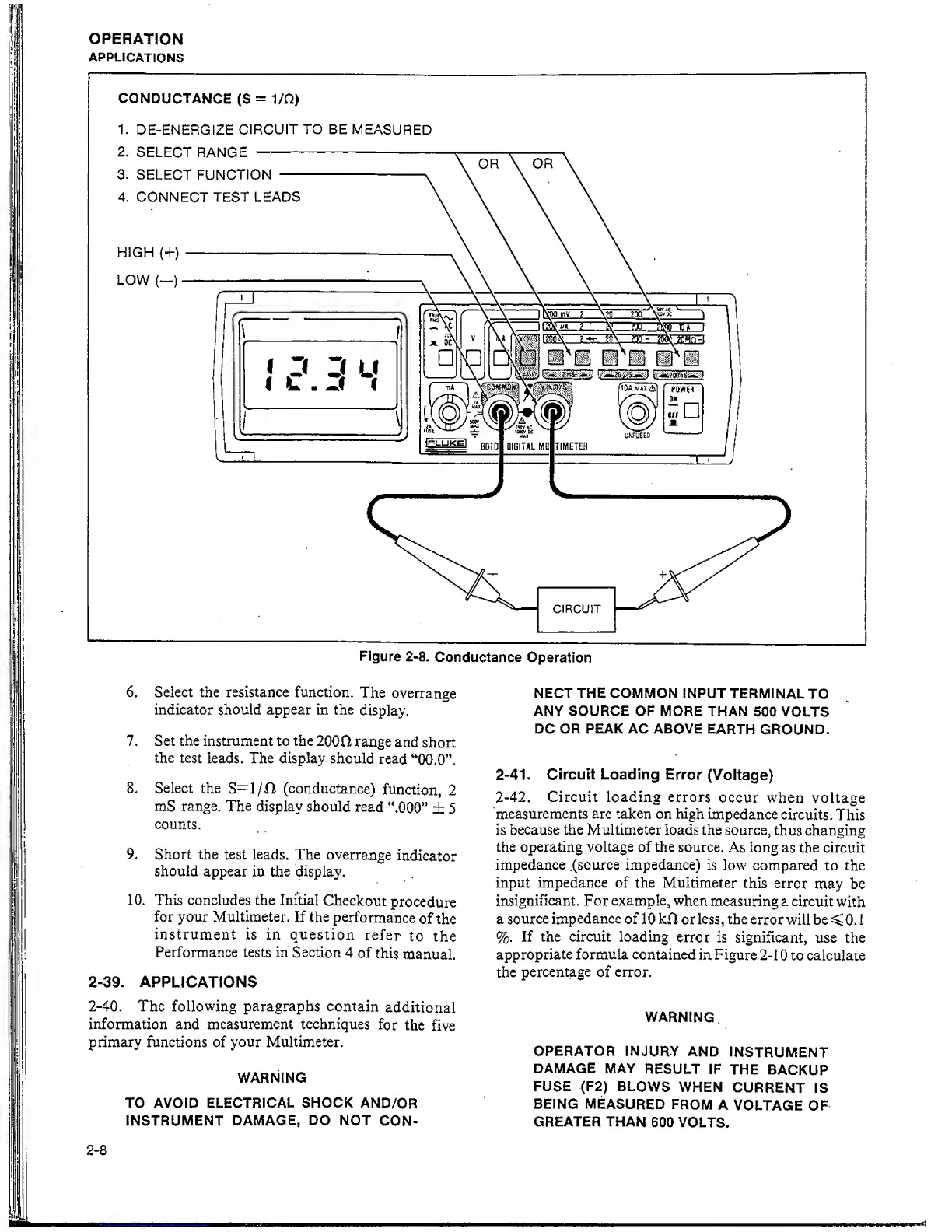
Figure
2-8.
Conductance
Operation
6. Select the resistance function.
The
overrange
indicator should appear in the
display.
7. Set the instrument to the
2000
range
and
short
the
test
leads. The display
should
read
“00.0”.
8. Select the
S=l/0 (conductance)
function,
2
mS
range. The
display should
read
“.000”
± 5
counts.
9.
Short the
test
leads.
The
overrange
indicator
should
appear in
the
display.
10. This concludes the Initial
Checkout
procedure
for
your Multimeter. If the
performance
of
the
instrument is in
question
refer
to
the
Performance tests in
Section
4
of this
manual.
2-39,
APPLICATIONS
2-40.
The
following
paragraphs
contain
additional
information and measurement techniques
for
the
five
primary functions of your Multimeter.
NECT
THE
COMMON INPUT
TERMINAL
TO
ANY SOURCE
OF MORE
THAN
500
VOLTS
DC OR
PEAK AC ABOVE
EARTH
GROUND.
2-41.
Circuit Loading
Error
(Voltage)
2-42.
Circuit loading errors
occur when
voltage
measurements are taken on high
impedance
circuits.
This
is
because the Multimeter
loads
the source,
thus
changing
the operating voltage of the source.
As long
as
the
circuit
impedance .(source impedance)
is
low compared to the
input impedance of the Multimeter
this error
may be
insignificant. For example,
when
measuring a
circuit
with
a
source
impedance of
10 kH or less, the
error
will be
^
0.
1
%.
If
the circuit loading
error is
significant,
use the
appropriate
formula
contained
in Figure
2-1
0
to calculate
the
percentage of error.
WARNING
OPERATOR
INJURY
AND
INSTRUMENT
DAMAGE MAY
RESULT
IF
THE
BACKUP
FUSE (F2)
BLOWS
WHEN
CURRENT
IS
BEING
MEASURED
FROM
A
VOLTAGE
OF
GREATER THAN
600
VOLTS.
2-8
WARNING
TO
AVOID ELECTRICAL
SHOCK
AND/OR
INSTRUMENT DAMAGE,
DO
NOT
CON-