OPERATION
SIGNAL
INPUT
LIMITS
2-18.
SIGNAL
INPUT
LIMITS
CAUTION
Exceeding the
maximum signal
input
limits
can
damage
the instrument.
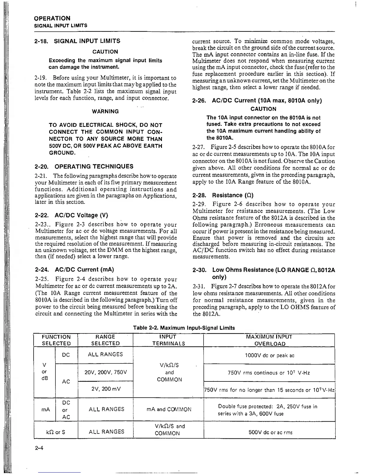
2-19,
Before
using
your Multimeter, it
is
important
to
note the maximum
input
limits that may
bg applied
to the
instrument. Table
2-2
lists the maximum
signal
input
levels
for
each
function, range, and input
connector.
WARNING
TO
AVOID
ELECTRICAL SHOCK,
DO
NOT
CONNECT THE
COMMON
INPUT
CON-
NECTOR TO ANY
SOURCE
MORE
THAN
500V
DC, OR
500V
PEAK
AC
ABOVE
EARTH
GROUND.
2-20.
OPERATING
TECHNIQUES
2-2
1 . The following
paragraphs
describe
how
to
operate
your Multimeter in each
of
its five primary
measurement
functions.
Additional
operating
instructions
and
applications are given in
the
paragraphs
on
Applications,
later in this section.
2-22.
AC/DC
Voltage (V)
2-23,,
Figure
2-3
describes how to
operate
your
Multimeter for ac or
dc
voltage measurements.
For all
measurements, select
the highest range
that
will
provide
the required resolution of
the
measurement.
If
measuring
an unknown voltage, set
the
DMM on the
highest
range,
then
(if
needed)
select a lower
range.
2-24.
AC/DC Current
(mA)
2-25.
Figure
2-4
describes
how to
operate
your
Multimeter
for
ac
or
dc current measurements
up
to 2A.
(The lOA Range
current measurement
feature
of
the
8010A is
described in
the following paragraph.)
Turn
off
power to the
circuit
being measured before
breaking
the
circuit and connecting the
Multimeter
in series
with
the
current
source.
To minimize
common
mode voltages,
break
the
circuit
on the ground
side of the current
source.
The
mA
input
connector contains
an in-line fuse. If the
Multimeter
does not respond when
measuring current
using
the mA
input connector, check the
fuse (refer to the
fuse
replacement
procedure
earlier
in this section).
If
measuring
an
unknown
current,
set the Multimeter
on the
highest
range,
then
select
a
lower
range if needed.
2-26. AC/DC Current (10A max,
801
OA
only)
CAUTION
The 10A input connector
on
the 801 OA is not
fused.
Take extra
precautions
to not exceed
the
10A maximum current
handling ability
of
the
8010A.
2-27.
Figure
2-5
describes how to operate the
8010A for
ac or
dc
current measurements up
to
lOA. The lOA input
connector on
the
8010A
is
not fused. Observe the
Caution
given above. All other
conditions
for
normal
ac or dc
current
measurements, given
in the preceding
paragraph,
apply to
the
lOA
Range feature
of the
80 10A,
2-28.
Resistance
(Q)
2-29. Figure
2-6
describes
how to operate
your
Multimeter for
resistance
measurements.
(The Low
Ohms
resistance
feature
of the 8012A
is described
in the
following
paragraph.) Erroneous
measurements can
occur if
power is
present in the
resistance
being measured.
Ensure
that power
is
removed
and the circuits are
discharged
before
measuring in-circuit
resistances.
The
AC/ DC
function switch has
no effect
during resistance
measurements.
2-30. Low Ohms Resistance
(LO
RANGE
Q,
801 2A
only)
2-3
1 .
Figure
2-7
describes
how to operate the
80 1 2A for
low
ohms resistance measurements.
All other conditions
for
normal
resistance
measurements,
given
in the
preceding
paragraph,
apply
to
the
LO
OHMS feature of
the 80 12A.
Table
2-2.
Maximum
Input-Signal Limits
FUNCTION
SELECTED
RANGE
SELECTED
INPUT
TERMINALS
MAXIMUM INPUT
OVERLOAD
V
or
dB
DC
ALL
RANGES
V/k^2/S
and
COMMON
1000V dc or peak
ac
AC
20V,
200V,
750V
750V rms continous
or
10"^
V-Hz
2V, 200 mV
750V rms for
no longer
than
15 seconds or
10'^V-Hz
mA
DC
or
AC
ALL
RANGES mA and
COMMON
Double
fuse
protected:
2A, 250V
fuse
in
series
with
a
3A,
600V
fuse
kf2 or
S
ALL
RANGES
V/kH/S
and
COMMON
500V dc
or ac rms