MAINTENANCE
GENERAL
INFORMATION
4-17.
DISPLAY
REMOVAL
4-18.
Use the following procedure to remove
the
LCD:
1. Preform the Main
PCB
Access
procedure.
2. Turn the instrument right side up.
3. Remove
the two screws that connect
the Main
PCB
Assembly and the Front Panel
Assembly.
The screws are
located at the
right front
of the
instrument.
4.
Carefully
slide the front panel
forward
until it
is
clear of the switches and
the
LCD.
Let
the
Front Panel
Assembly
drop
clear of the
LCD.
5. Remove the two screws connecting
the
LCD to
the Main PCB Assembly.
6. Place your fingernail under the grey
tabs on
the
display frame and lift
them
free
of the
screwposts
on
the
display mounting
bracket.
7. Rotate the display frame
forward
and
down
until
the
two
hooks on the bottom
of the
display
frame
release the display
mounting
bracket.
8.
The
LCD may now
be
lifted
free
from
the
display mounting bracket.
9 . A small
length
of flat, flexible
material
may
fall
out. This is the “zebra strip”
an elastomeric
strip
of
alternate
areas of conductive
and
non-
conductive
material. When the
screws
are
tightened to hold down the
display
assembly,
the
zebra strip provides electrical
contact
between the
pins
on the LCD and
the land
pattern on the Main PCB.
The zebra
strip
is
located in a channel on the
display
mounting
bracket.
10. To reassemble, reverse
the
previous
procedures
in
a
logical order.
4-19.
Cleaning
CAUTION
Do not use
aromatic
hydrocarbons
or
chlorinated solvents
for
cleaning.
These
solutions will react
with
the
plastic
materials
used in the instrument.
CAUTION
Do
not get the liquid
crystal
display wet.
Remove
the
display assembly before washing
the
pcb
and do not
install
it
until
the pcb has
completely
dried.
4-20.
Clean
the front panel and case
with
a
mild
solution
of
detergent and water. Clean
dust
from
the circuit
board
with
clean,
dry,
low
pressure air
(<20
psi).
Contaminates
can be
removed
from the pcb
with
demineralized
water
and a soft brush (remove the
LCD
before
washing
the
Main PCB Assembly and
avoid
getting
excessive
amounts of
water
on
the
switches).
Dry
with clean,
dry,
low pressure air,
and
then
bake at
50°
C to
60°
C (124°
F to
140°F) for 24
hours.
4-21.
Special Test Devices
4-22.
There are two devices
which
you can
make
that
will improve the efficiency
and accuracy
of the
Calibration Procedure. The
two
devices are
the
190 Test
Set and the 1.90 Test Set.
They insure
good electrical
contact and consistent
results.
The following
paragraphs
describes
the
construction
of the
Special
Test
Devices.
4-23.
1
90 TEST SET
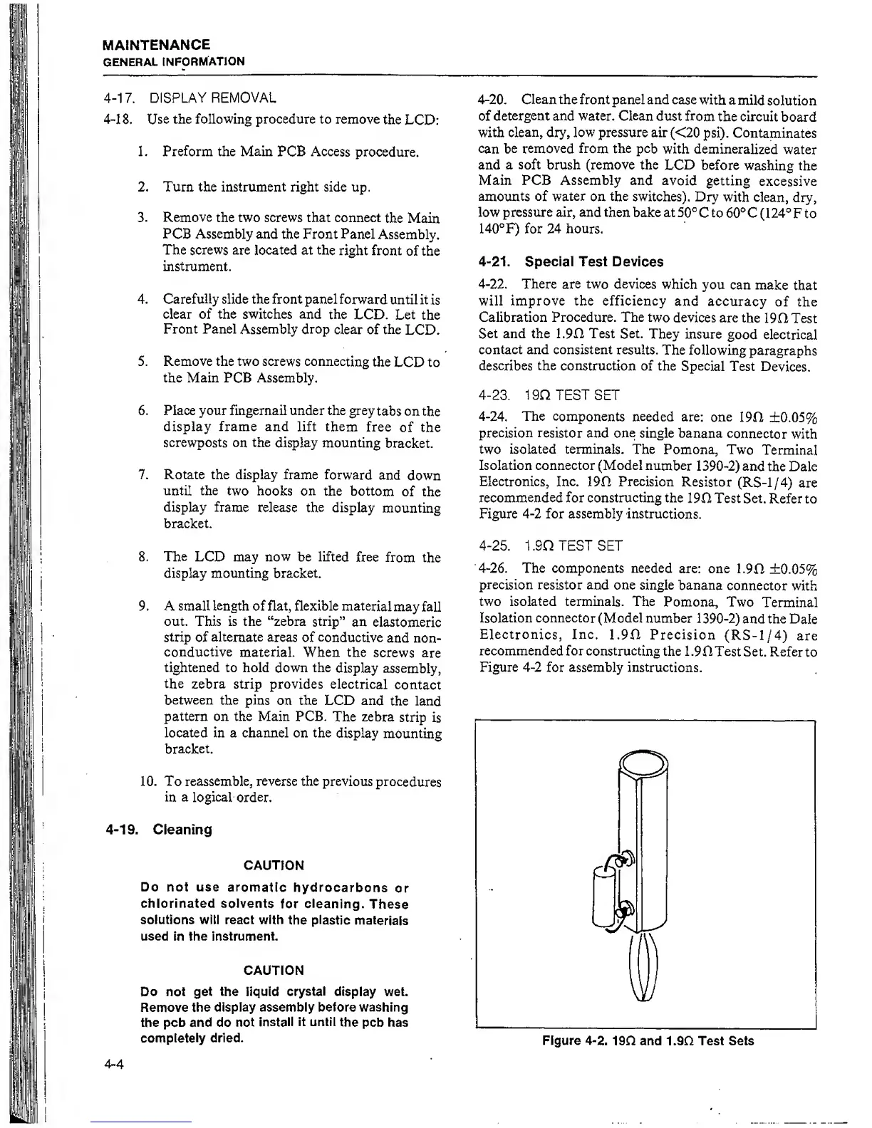
4-24.
The
components needed
are:
one
190
±0.05%
precision resistor
and
one
single banana
connector
with
two
isolated terminals.
The Pomona,
Two
Terminal
Isolation connector (Model
number
1390-2)
and
the Dale
Electronics, Inc.
190
Precision
Resistor
(RS-1/4)
are
recommended for constructing the
190 Test Set.
Refer to
Figure
4-2
for assembly instructions.
4-25.
1 .90 TEST SET
4-26.
The components needed
are: one
1.90
±0.05%
precision resistor
and one single
banana
connector
with
two isolated terminals. The
Pomona, Two
Terminal
Isolation connector
(Model
number
1390-2) and the
Dale
Electronics, Inc.
1.90 Precision
(RS-1/4)
are
recommended for
constructing
the
1.90 Test
Set. Refer
to
Figure
4-2
for
assembly instructions.
Figure 4-2.
190 and 1.90 Test
Sets