OPERATION
INITIAL
CHECKOUT
PROCEDURE
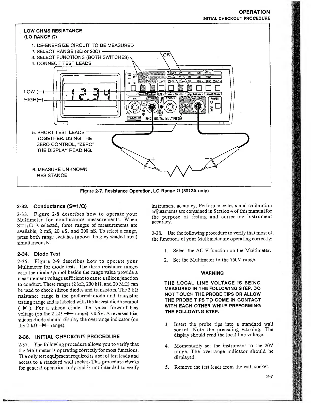
LOW
OHMS
RESISTANCE
(LO RANGE O)
1,
DE-ENERGIZE CIRCUIT TO BE MEASURED
Figure
2-7.
Resistance Operation, LO
Range
O.
(801
2A only)
2-32. Conductance (S=1/Q)
2-33. Figure
2-8
describes
how to operate
your
Multimeter
for
conductance
measurements.
When
S=l/n
is
selected,
three ranges
of measurements are
available, 2
mS,
20
juS,
and
200
nS. To select a range,
press
both
range
switches (above
the grey-shaded
area)
simultaneously.
2-34.
Diode
Test
2-35. Figure
2-9
describes
how
to
operate
your
Multimeter
for
diode
tests.
The three resistance
ranges
with
the diode
symbol beside
the range
value
provide a
measurement
voltage
sufficient to cause a siliconjunction
to
conduct.
These
ranges
(2
kfi, 200
kfl, and
20
MH) can
be used
to
check silicon
diodes
and transistors. The
2
kO
resistance
range
is the
preferred diode and
transistor
testing
range
and is
labeled with
the largest diode
symbol
(-N-).
For
a silicon
diode,
the typical forward
bias
voltage
(on
the 2 kfl
-W- range) is 0.6V. A reversed
bias
silicon
diode
should
display
the overrange indicator (on
the 2 kfl
“I—
range).
2-36. INITIAL
CHECKOUT
PROCEDURE
2-3
7 .
The
following
procedure, allows you to verify that
the
Multimeter
is
operating
correctly for most functions.
The only
test
equipment
required
is
a
set of test leads
and
access
to a
standard
wall
socket.. This
procedure
checks
for
general
operation
only and is
not intended to
verify
instrument
accuracy.
Performance tests and
calibration
adjustments
are contained in
Section
4 of this manual for
the
purpose of
Testing and
correcting
instrument
accuracy.
2-38. Use
the following
procedure to
verify that most of
the
functions
of your
Multimeter are
operating correctly:
1.
Select the AC
V function on the Multimeter.
2. Set
the Multimeter to the
750V
range.
WARNING
THE
LOCAL LINE VOLTAGE IS BEING
MEASURED
IN THE FOLLOWING
STEP. DO
NOT TOUCH
THE PROBE TIPS OR ALLOW
THE
PROBE TIPS TO COME IN
CONTACT
WITH EACH OTHER WHILE
PREFORMING
THE
FOLLOWING STEP.
3.
Insert the probe tips
into
a standard wall
socket. Note the
preceding
warning. The
display
should read
the local line
voltage.
4.
Momentarily set the
instrument
to the
20V
range.
The overrange
indicator
should
be
displayed.
5.
Remove
the test leads
from
the
wall
socket.
2-7