Forma Scientific, Inc.
_________________________________________________________________________
5-10
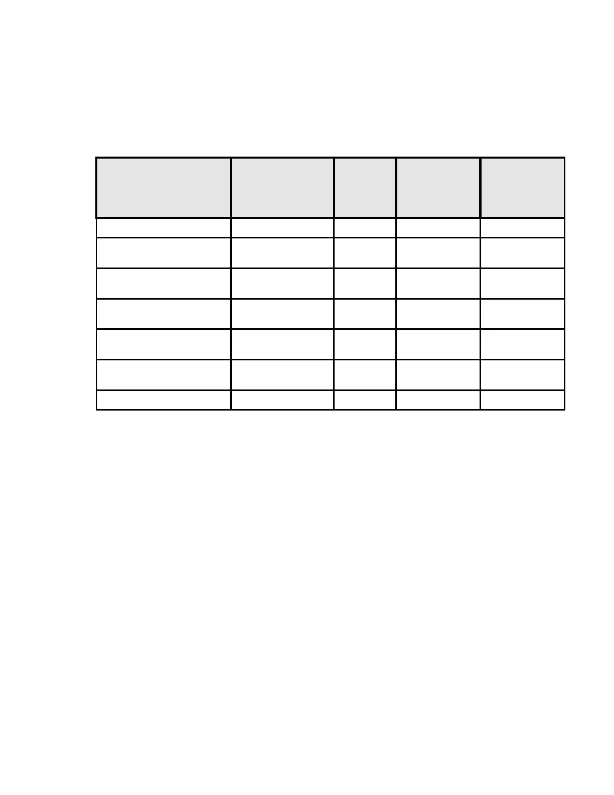
Alarms and Indicators, Table 5-1
Alarm Condition Visual
Indicator
Audible
Alarm
Reset Delay
(Ringback)
Alarm
Relay
State
None Off Off
On
*
Temp.> Over
Temp Setpoint
Over Temp
LED On
On 30 Minutes
Off
*
Low Water in
Water Jacket
Flash Add
Water LED
On 30 Minutes
Off
**
% CO
2
Dev
Setpoint ± 1%
CO
2
Alarm
LED On
On
Off
***
Tank1 Low Pressure Low
#1
On
Off
***
Tank2 Low Pressure Low
#2
On
Off
Power Failure Off Off
Off
*
Silenced audible alarm will ring back in 30 minutes if the alarm condition still
exists. The Alarm LED will remain lit.
**
Condition must exist for four minutes before alarm activates. Silenced alarm will
extinguish the led alarm light, silence the audible alarm and change the alarm relay to the
on state.
***
When the CONTROL switch on the gas guard is turned off the indicator light will
be extinguished and the audible alarm will be silenced. The built-in alarm relay on the
Model 3158, however, remains active.
A SPDT relay is provided for monitoring alarm conditions on the incubator.
Connections are made by means of an RJ-11, telephone style jack, located on the rear of
the cabinet. Figure 5-7 shows the connector wiring diagram. Any of the incubator alarms
will activate the relay.