21
TABLE OF CONTENTS
SECTION 1. Description and specifications of the
machine
1.1 Foreword....................................................... 22
1.2 Warranty....................................................... 22
1.2.1 Warrantyexclusions..................................... 22
1.3 Identicationofthemachine......................... 23
1.4 Descriptionofthemachineandauthorized... 23
1.4.1 Useofthemachine....................................... 23
1.4.2 Unauthorizeduseofthemachine.................. 24
1.4.3 Controlanddrivingposition.......................... 24
1.5 Protectionsandsafetydevices...................... 24
1.5.1 Noiselevel..................................................... 24
1.5.2 Vibrationslevel............................................. 24
1.6 Techincalspecications................................ 24
SECTION 2. Safety and prevention
2.1 Safety............................................................ 25
2.1.1 Wordsused................................................... 25
2.1.2 Generalsafetyregulation.............................. 26
2.2 Safetysignals................................................ 26
2.3 Safetywhileoperatingandmaintenaing........ 26
SECTION 3: Transport
3.1 Transport...................................................... 27
SECTION 4: Use
4.1 Beforeusingthemachine............................. 28
4.1.1 Adjustmentofthehandlebars....................... 28
4.1.2 Wheels.......................................................... 29
4.1.3 Installationgearboxrodandclutch............... 29
4.1.4. Replacementintercangeableequipment........ 29
4.1.5 Preliminarychecks........................................ 30
4.2 Starting......................................................... 30
4.3 Forwardmovement-shifting........................ 31
4.3.1 Reverse......................................................... 31
4.4 Duringoperation........................................... 31
4.4.1 Useofthemachineeonslopes..................... 32
4.4.2 Parking.......................................................... 32
4.5 Differentiallocking........................................ 32
4.6 Powertakeoff................................................ 32
4.7 Stoppingoftheengine.................................. 32
4.8 Afteruse....................................................... 33
SECTION 5: Routine maintenance
5.1 Generalinformation...................................... 33
5.2 Enginemaintenance...................................... 33
5.3 Machinemaintenance................................... 33
5.3.1 Adjustmentoftheclutchcontrol................... 33
5.3.2 Adjustmentoftheacceleratorcontrol........... 33
5.4 Extraordinarymaintenance........................... 33
5.5 Settingatrest................................................ 34
5.6 Machinedismantling..................................... 34
5.7 Spareparts................................................... 34
5.8 Troubleshooting............................................ 34
Declarationofconformity.......................................... 35
DESCRIPTION OF FIGURES
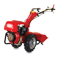
Figure 1 - Overview of the tiller.
1) Nameplate.
2) Powerunit.Duetoitscharacteristics,seethein-
structionmanualattached.
3) Transmission.
4) Drivewheels.
5) Steeringhandles.
6) Housinginterchangeableequipment.
7) Clutchlever.Pressed,afterhavingdisengagedthe
lockingdevice15permitstheengaginganddisen-
gagingtheclutch.
8)Lever forlocking/unlockinglateralrotationand
inversionhandlebars.
9) Leverthrottle/engineoff.
10) Reverserlever.Letsreversethedirectionofrota-
tionandtherotationofthePTO.
Toinsertthelever,itisnecessarytoliftthering
underneaththehandle(seeFigure1A).
11) Rodgearchange(3forwardand3reverse).
12) Auctionengaging/disengagingthePTO.
13) Handlebarheightadjustmentlever.
14) Handlebarcontrolrecoilstarter.
15) Deviceforlockingclutchlever.
16) Shut-offengine(diesel):
B:Engineoff,C:Motorrunning.
17) Differentiallocklever.
Figure 2 - Dimensions.
Figure 3 - Gearbox.
1) Transmissionoillevelplug.
2) Transmissionoildrainplug.
3) Ventplugandll/relltransmissionoil.
4) Treedoorwheels.
Figure 4 - Adjusting the clutch.
1) Locktheclutchcable.
2) Registerclutchcable.
3) Screwtheendoftheracetheclutchlever.
4) DowelpinlockandPTOshifterrods.
5) Clutchlever.
Figure 5 - Starting the engine.
1) Manettinocontrolrecoilstarter.
2) Switchtheadditionalconsentofgoodwill(ifany).
3) Fueltankcap.
Figure 6 - Engagement interchangeable equipment.
1) Leversnaplockinterchangeableequipment.
2) Housinginterchangeableequipment.
7 - Reversing handlebars.
1) Auctionengaging/disengagingthePTO.
2) Rodgearchange(3forwardand3reverse).
3) AttachingPTOshaft.
4) Couplingrodspeed.
5) Springpinlockingrods.
6) Adhesivesignalingthedirectionofrotationforthe
reversalofthehandlebars.
7) Throughholesofsupportrods(No.2).
Figure 8 - A)machinewithmillingunit. B) Machinewith
invertedhandlebarsandcutterbar.
9 - Attachment points lifting machine.
Figure 10 - Safety signs and their location on the ma-
chine(fortheirdescriptionsee2.2Safetysigns).
ENGLISH
 Loading...