29
Thenreleasethelever(8Fig.1).Therewillbeone
positionto theright,1left positionandacentral
location(amachinealreadyinstalled).
Rotatethehandlebars180degrees
To be able to apply interchangeable equipment
fronts(egmower,snowblower,etc..),Youmust
placethehandlebarsabovethebonnet,proceedas
follows:
1)Removethespringpins(5Fig.7)thatlockwhen
theshiftrodsandshiftPTOengaged.
2)Removetherods(1and2Fig7)fromtheirseats
andmovethemsothattheyarenotintheway.
3)Pullthelever(8Fig.1)androtatethehandlebars
180degreesuntilyoundtherightlatches.Then
againrilascirethelever(8Fig.1).
N.B.Toavoiddamagingthecontrolcables,the
rotationmustbecarriedoutaccordingtothedi-
rectionindicatedbythepictogramsonthema-
chine(Fig.67:06Fig.10).
Turnthehandlebars180degrees,reverseauc-
tionsare1and2,Fig7,whichoperatethePTO
levertheleverselectionmarc.
CAUTION
The rods (1 and 2 Fig 7 ) should not be fashion
shows from the hole of support ( Fig. 7 7).
4)Re-insert the control rods(1and 2 Fig 7) and
lockintheirseatswiththespecialspringpins(5
Fig.7).
4.1.2 WHEELS
Themachineisprovidedwithapairofwheelsthat
canbeofthexeddiscoradjustabledisctypede-
pendingonthecustomer'srequest.Thewheelsare
usuallynotttedonthemachine.
Proceedasfollowstotthewheels:
-Raisethemachine(seechap.3.1“Transport”).
-Fitthewheelsontotheshaft(4Fig.4)-oneper
side - and check that the assembly direction is
correct.
-Alignthewheeldriveandlockingholewiththatof
theshaft.
-Insertthewheellockspringpinprovidedstand-
ard.
Ifthewheelsareadjustableitispossibletosetthe
machinewheelbaseatthreedifferentwidths;thisde-
pendsonhowtheinternaldiscispositioned.
Verifythatthemountingofthewheelsiscorrect,and
thatthearrowstampedonthetire,correspondsto
thedirectionofadvanceofthemachine,otherwise
reversethewheels.
4.1.3 INSTALLATION GEARBOX ROD AND CLUTCH
ENGAGEMENT
Forreasonsofpackingtherodsabove,aredropped
fromtheircontrollevers(1and2Fig.7),afterplac-
ingthehandlebarstotyourneeds,inserttherods
intotheholesofsupport(7Fig.7)andthentuckthe
tailintheirseats(3and4Fig.7)andthenlockthem
withtheappropriatespringpins(5Fig.7).
CAUTION
Fit the rods as indicated on the diagram «A» and
«B» in Figure 8.
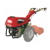
4.1.4 REPLACEMENT OF THE
INTERCHANGEABLE EQUIPMENT
The replacement of the equipment must be well
with the engine off and the car locked.
Toreplacetheinterchangeableequipment,youwill
haveto:
- Lockthemachineinasafeway,pushthelever(1
Fig.6)untiltheend,thentaketheequipmentout
swayingittoeaseitsremovalandputitaside.
- Taketheequipmenttobeassembled,insertitinto
itshousing(2Fig.6)andpushituntiltheend.
- Liftthelever(1Fig.6)andcheckthatitisproperly
locked(theclamphastogo7-8mmdownandthe
leverhastobekeptlifted)
- When PTO is actuated for the rst time after
changing an equipment, operate the clutch
control lever slowly in order to be able to easily
insert the grooved bush connecting the machine
and the new equipment.
DANGER
Before inserting the equipment into its housing,
make sure that the cylindrical part is clean and
well lubricated with grease. Avoid damaging the
PTO connecting sleeve.
This operations must be carried out by two people
wearing strong gloves.
All the towed accessories (plough, tank, trailer)
must be connected to the motor cultivator at the
cupling (8 Fig. 5) with the special pin and its
safety pin.
ENGLISH
 Loading...