Foundry Hardware Installation Guide for the FES, FESX, and FWSX
7 - 8 © 2008 Foundry Networks, Inc. December 2008
Pinouts and Signaling
This section lists the pinouts for the DB-9 connector and RJ-45 port jacks.
Serial (Console) Port Pinouts
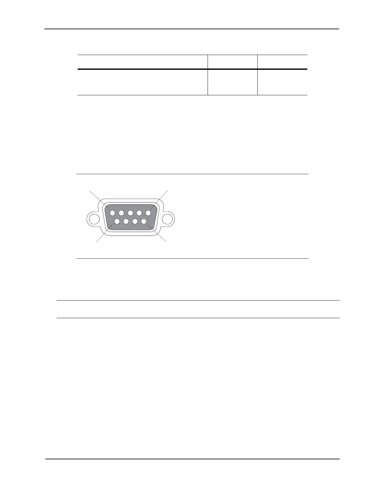
The Console port is a standard male DB-9 connector, as shown in Figure 7.1.
Figure 7.1 Serial Port Pin and Signalling Details
Most PC serial ports require a cable with a female DB-9 connector. However, terminal connections will vary,
requiring a cable with either a DB-9 or DB-25 connector, male or female.
Serial cable options between the chassis and a PC or terminal are shown in Figure 7.2.
NOTE: As indicated in Figure 7.1 and Figure 7.2, some of the wires should not be connected. If you do connect
the wires that are labeled “Reserved”, you might get unexpected results with some terminals.
FESX628E-PREM6 or FESX648 + one 10 GbE
uplink + two XFPs + four SFPs + two RPS5
power supplies
40
° C
118,947
Table 7.5: MTBF for the FastIron Compact Switches
Configuration / Module Temperature MTBF (hours)
1
5
96
Pin Assignment
DB-9 male
Pin Number
1
2
3
4
5
6
7
8
9
Switch Signal
Reserved
TXD (output)
RXD (input)
GND
CTS (input)
RTS (output)
Reserved
Reserved
Reserved
1
5
96
Pin Assignment
DB-9 male
Pin Number
1
2
3
4
5
6
7
8
9
Switch Signal
Reserved
TXD (output)
RXD (input)
GND
CTS (input)
RTS (output)
Reserved
Reserved
Reserved