F3D3 Series Service Manual Parts Adjustment / Section 3.6
Questions? Call Franke Technical Support Group For Your Area. Copyright 2012 Franke, Inc. All rights reserved.
3.6 Activate Backup Temperature Display –
Change Control Board Cable Jumpering
Problem: Freezer is operating but compartment temperature
does not appear in left lane display.
NOTE: For F3D3 Models manufactured after November
2011, See page 2 for Cableless Jumper Wire Connector
Instructions. For all other models…
1) Disconnect power at outlet. [Pull plug.]
2) Use a medium Phillips screwdriver to remove the four
M5 (two-left, two-right) control panel mounting screws.
3) Pull panel cover/bezel straight out and set aside. NOTE:
you do NOT need to remove Plexiglas touchpad panels.
4) Locate the three terminal connections on the right side of
the Left Lane Main Control Board labeled: B-B / LON,
RELAY and TEMP PROBE. These three connections
direct compartment temperature to left lane display.
5) Remove Master 12-pin B-B (board-to-board) cable
connector from left
Lane Control Board. See Photo 2
6) Remove Slave 12-pin B-B connector from right Lane
Control Board.
7) From right Lane Control Board, carefully pull harness out
and under the right broad. Extra harness is provided.
8) When 12-pin (Master) B-B connector extends past right
broad, connect it to right Lane (B-B) terminal.
9) Route (Slave) 12-Pin B-B connector and cable back
under right Lane Control Board and connect to left Lane
(B-B) terminal. Tip: A 14” [36 cm] wire fish will help pull
harnesses behind right broad, which is mounted on
standoff studs.
10) Remove (Master) 3-pin, 2-wire RELAY cable connector
from left Lane Control Board.
11) From right Lane Control Board, carefully pull harness out
and under the right broad. Extra harness is provided.
12) When 3-pin, 2-wire RELAY connector extends past
broad, connect it to the right Lane RELAY terminal.
13) Disconnect 2-pin TEMP PROBE connector from left
Lane control broad.
14) Pull out extra harness and route connector under right
Lane control broad until you have enough harness to
connect 2-pin connector to TEMP PROBE terminal.
15) Position cover/bezel over lane touch pads and align with
left and right side mounting holes.
16) Secure cover/bezel with the four screws removed earlier.
17) Plug in unit power cord to power supply.
Continued…
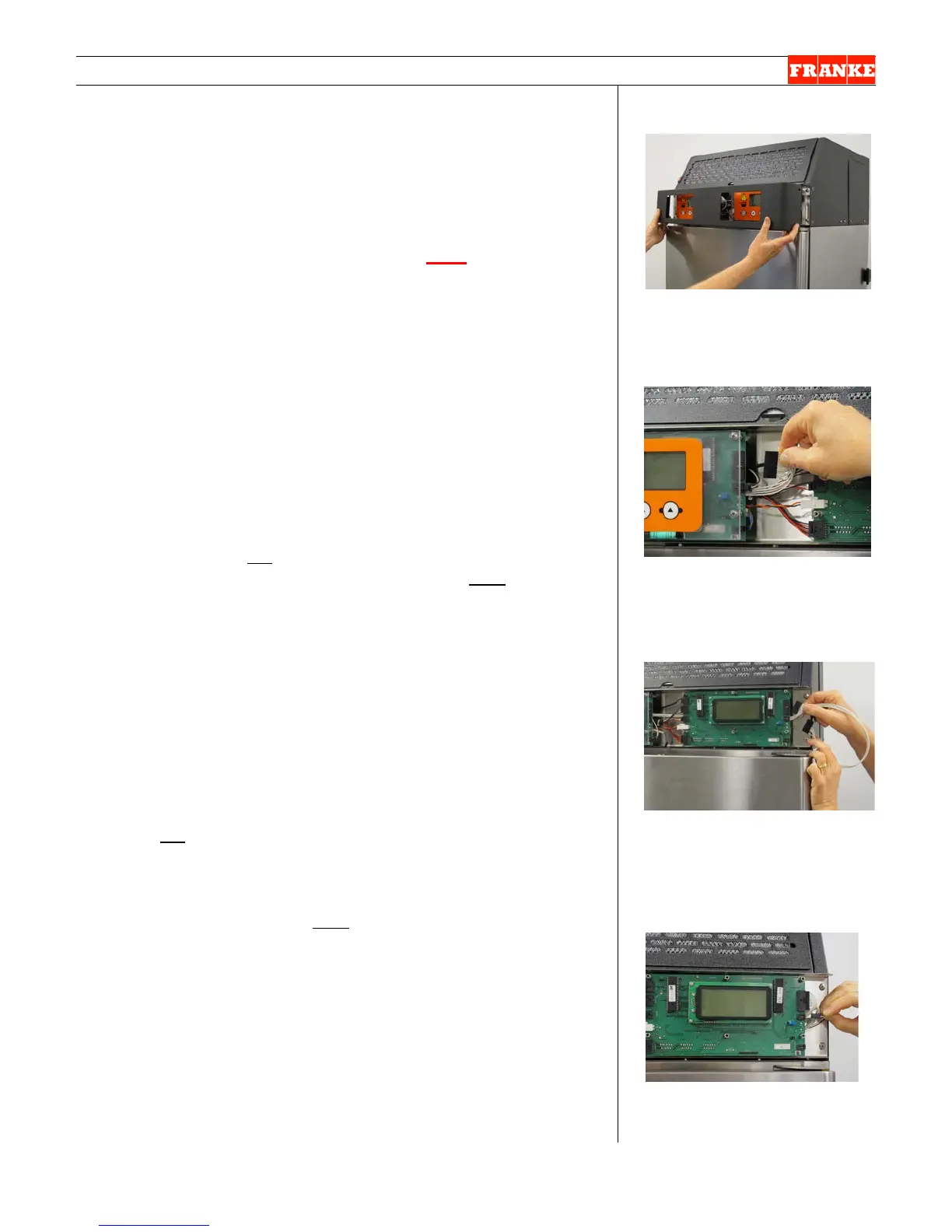
[Photo 1]
Remove four front control panel
cover/bezel screws & pull off
cover/bezel.
[Photo 2]
Remove 12-pin (Master) B-B
connector from left main control
board.
[Photo 3]
with touchpad removed
Disconnect 12-pin B-B connector
from right control board and pull
Master terminal through to right
control broad.
[Photo 4]
Connect 12-pin B-B Master & 3-
pin, 2-wire RELAY-to-right-main-
control-board terminals.
 Loading...