Part number 550-142-950/0122
101
FreeStyle
®
series
2
wall mount gas-fired water boiler – boiler manual
37 Troubleshooting (continued)
Figure 127 “tS” - Transparent Parameter mode for FreeStyle
®
boilers (continued)
By pressing the “reset” push button for 1 second, it is possible to escape from the “Transparent parameter” mode. By pressing the
“reset” push button for 20 seconds, it is possible to leave the Installer mode. If no action has been taken, the MMI automatically
leaves this mode aer 15 minutes.
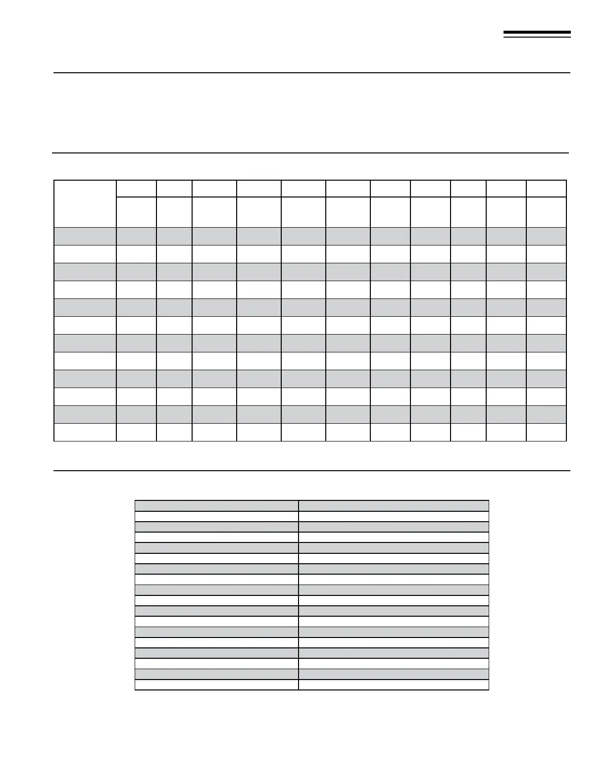
Figure 128 Default Control Board “Transparent Parameters” for FreeStyle
®
boilers
Figure 129 “In” - Inquiry mode for FreeStyle
®
boilers
t01 blinking
CH Supply sensor1 Temperature (°F) between 32 and 257
t02 blinking
CH Supply sensor2 Temperature (°F) between 32 and 257
t03 blinking
CH Return sensor Temperature (°F) between 32 and 257
t04 blinking
DHW sensor Temperature (°F) between 32 and 257
t05 blinking
Outdoor sensor Temperature (°F) between 22 and 158, blinking if it is negative
t06 blinking
Exhaust sensor Temperature (°F) between 32 and 257
F07 blinking
Actual Blower Speed (Hz) Min=00, Max=parameter depending
L08 blinking
Actual burner load (%) 00%=Min, 125%=Max DHW boost output
F09 blinking
Actual water ow rate (=l/min *10) between 00 and 255
“In” as Inquiry mode
Selecting “In” the display starts with showing “t01” blinking. By means of the CH+ and CH- push buttons it is possible to select the
parameters; between “t01” and “F13”. Selecting one of these parameters, by means of the DHW+ and DHW- push buttons is pos-
sible to see his value (not ashing; only in case of negative outdoor temperature the value is ashing).
Boiler
Model
“b01” “b02” “b04” “b05” “b06” “b10” “b12”
“b22”
“P01” “P02” “P04”
Gas
type
Boiler
type
Fan
Max. Freq.
in DHW
Fan
Max. Freq.
in CH
Fan
Min. Freq.
in CH
S/W mode
selection
button
Var. Out
Relay
Vent
material
Ignition
level
CH Slope
(F/min)
CH
Off Time
FS-80-N-C
0=Nat. gas
3 155 155 35 1 0 1 80 6 2
FS-120-N-C
0=Nat. gas
3 200 200 40 1 0 1 60 6 2
FS-155-N-C
0=Nat. gas
3 210 210 39 1 7 1 50 6 2
FS-80-N-H
0=Nat. gas
2 155 155 35 1 0 1 80 6 2
FS-120-N-H
0=Nat. gas
2 200 200 40 1 0 1 60 6 2
FS-155-N-H
0=Nat. gas
2 210 210 39 1 0 1 50 6 2
FS-80-LP-C
1=LPG
3 145 145 35 1 0 1 80 6 2
FS-120-LP-C
1=LPG
3 185 185 40 1 0 1 60 6 2
FS-155-LP-C
1=LPG
3 220 220 40 1 7 1 50 6 2
FS-80-LP-H
1=LPG
2 145 145 35 1 0 1 80 6 2
FS-120-LP-H
1=LPG
2 185 185 40 1 0 1 60 6 2
FS-155-LP-H
1=LPG
2 220 220 40 1 0 1 50 6 2