Part number 550-142-950/0122
29
FreeStyle
®
series
2
wall mount gas-fired water boiler – boiler manual
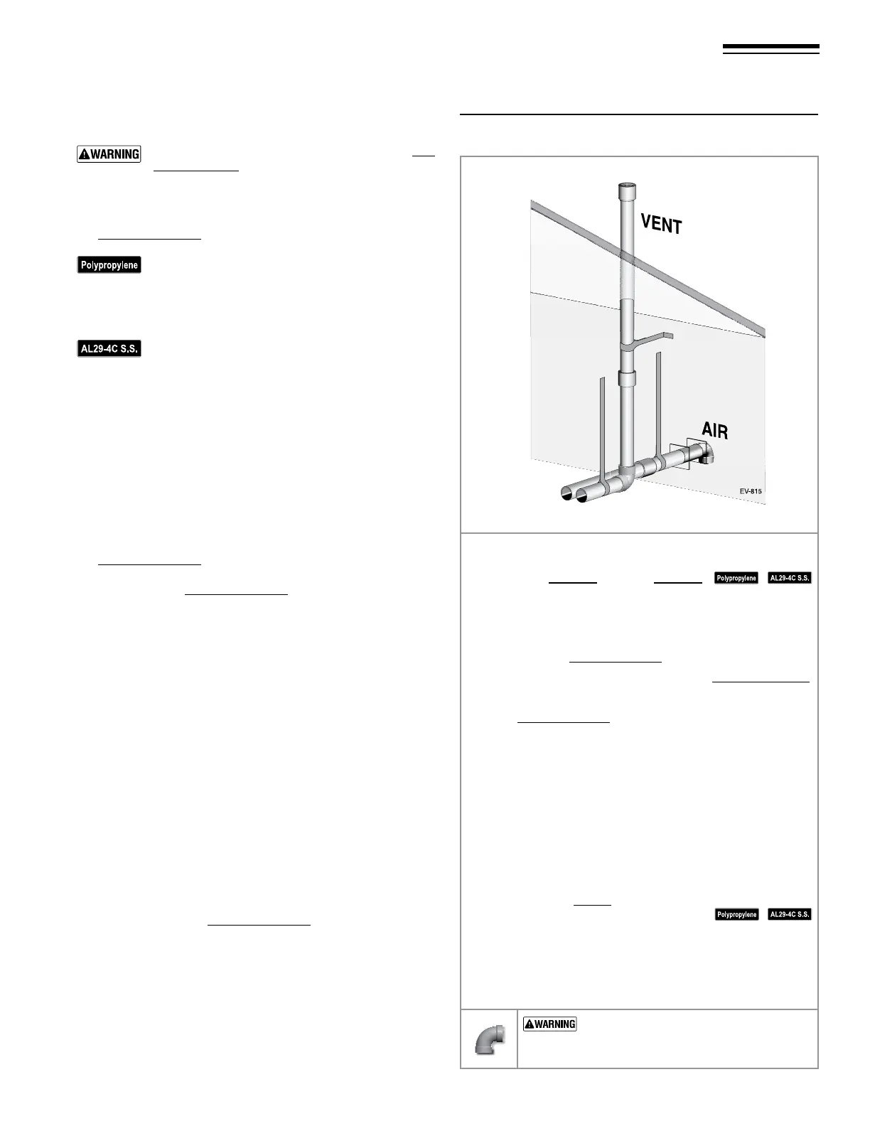
Figure 35 INSTALLATION SEQUENCE — Vertical vent/
sidewall air
Allowable vent/air pipe materials & lengths
Use only the vent materials and kits listed in Fig-
ure21,page17. Provide pipe adapters if specied.
1. Locate the terminations such that the total air pip-
ing and vent piping from the boiler to the termina-
tion will not exceed the maximum length given in
Figure20,page16.
For polypropylene applications, comply with any
additional requirements in the vent system manu-
facturer’s instructions. (Do Not use 3”PVC transi-
tion pieces at the boiler vent and air connections).
Install a locking collar at every joint.
For AL29-4C vent pipe applications, comply with
any additional requirements in the vent system
manufacturer’s instructions. Provide a AL29-4C
starter piece from the AL29-4C manufacturer to
the transition piece at the boiler vent connection.
e air piping must be PVC or CPVC. Provide a
3”PVC transition piece at the boiler air connection
if using 2” air piping.
2. For 3” to 2” transitions, must use appropriate vent material.
For polypropylene or stainless steel must use approved sup-
pliers transitions.
Determine termination location
1. e air and vent terminations must be installed as shown in
Figure30,page25.
2. e terminations must comply with clearances and limita-
tions shown in Figure22,page19.
3. Locate the terminations so they are not likely to be damaged
by foreign objects, such as stones or balls, or subject to buildup
of leaves or sediment.
Prepare roof penetration
1. Vent pipe penetration:
a. Cut a hole for the vent pipe. For either combustible or
noncombustible construction, size the vent pipe hole at
least 0.4” larger than the vent pipe diameter.
b. Insert a galvanized metal thimble in the vent pipe hole.
2. Follow all local codes and vent pipe manufacturer’s instruc-
tions for isolation of vent pipe when passing through oors,
ceilings and roofs.
3. Provide ashing and sealing boots sized for the vent pipe and
air pipe. Follow all vent pipe manufacturer’s instructions.
Vent termination and ttings
1. Prepare the vent termination coupling by inserting a bird
screen. Bird screens must be purchased separately. See the
parts list at the end of this manual for part numbers.
2. Maintain the required dimensions of the nished termination
piping as shown in Figure36,page30.
Multiple vent terminations
1. When terminating multiple boilers, terminate each vent/air
connection as described in this section.
2. Place adjacent terminations at least 6 inches apart.
14 DIRECT VENT — Vertical vent /sidewall air
Step 1 Read and follow all instructions in this manual. DO NOT
proceed with vent/air installation until you have
read page 15 through page 20.
See notices at le.
Step 2 Install the boiler in a location that allows proper routing of
all vent and air piping to the selected locations.
Step 3 Make sure the selected vertical termination location com-
plies with Figure22,page19
Step 4 Use only the vent materials listed in Figure21, page17.
Provide pipe adapters where required. Vent piping and
air piping lengths must not exceed the values shown in
Figure20,page16.
Step 5 Prepare the vertical penetration (vent) and sidewall penetra-
tion (air) and secure penetration components as instructed
in this section.
Step 6 e air piping must terminate in a 90-degree down-turned
elbow as shown above. e vent piping must terminate in
a coupling pointed upward as shown above.
Step 7 Install vent and air piping between the boiler and the air
and vent terminations. Slope horizontal piping downward
toward the boiler at least 1/4 inch per foot. Install pipe sup-
ports every 5 feet on both the horizontal and vertical runs.
Install a hanger support within 6inches of any upturn in the
piping. See page30 for general guidelines. Also comply with
vent pipe manufacturer’s instructions.
See notices at le.
Step 8 Insert the vent and air piping through the penetrations and
secure the termination ttings.
Step 9 Maintain clearances shown in this section. Vent and air
terminations must be tted with bird screens as shown.
USE SWEEP ELBOWS FOR ALL VENT
AND AIR PIPING — DO NOT use short radius
elbows for vent or air piping. Boiler performance
could be aected.