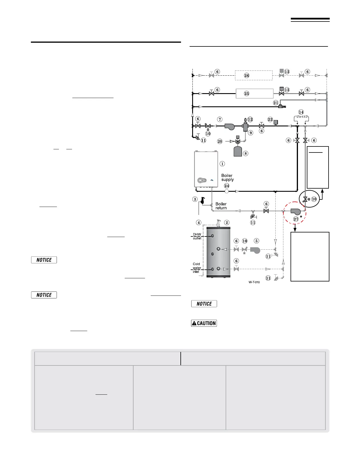
Figure 54 Zone valve zoning — primary/secondary
connection — a system circulator is required
LEGEND for Figure 54.
Note: This is a common legend for all piping diagrams, Not all
items listed appear in every gure.
1 FreeStyle® wall mount boiler
2
I
ndirect Water Heater, if used
3
Relief v
alve, eld piped — MUST be piped to boiler
return connection on Combi boilers, Heating Only boilers
relief valve eld piped on supply.
4
Relief v
alve piping to drain — see page42
5 DHW circulator
6
I
solation valves
7
S
ystem circulator
8
E
xpansion tank, diaphragm type, if used
9
A
ir separator
10
Flo
w/check valves
11
Pur
ge/drain valves
(Installer supplied)
12 Auto air vent
13
Z
one valves
14
P
rimary/secondary connection (tees no more than
12 inches apart)
15 E
xpansion tank, closed type, if used (some chiller
systems may use a diaphragm-type expansion tank)
16 Water chiller
17
Ch
eck valve
18 Y-strainer
19 Balancing valve
20
M
ake-up water supply – Use applicable codes to
determine if backow preventers, pressure reducing
valves, and ll valves may be required
21
B
y-pass pressure regulator, REQUIRED for zone valve
systems unless other provision is made
22
H
igh limit temperature control
23
Z
one circulator
24
P
ressure/temperature gauge, supplied with boiler, eld
piped
25
H
eating circuits
26
A
dditional heating circuits, if any
27
B
oiler circulator,
*
(For Heating Only boilers, In the
Combi boiler the circulator is already inside the
boiler jacket).
28 Mixing valve, if any
Part number 550-142-950/0122
43
FreeStyle
®
series
2
wall mount gas-fired water boiler – boiler manual
18 Primary/Secondary System Piping (continued)
Zone Valve zoning – primary/secondary
(Shown with optional DHW piping)
See Figure54.
1. is conguration is for zone valve systems using a boiler
loop connected as a secondary circuit o of a primary system
loop. Systems whose ow characteristics do not comply with
those listed in Figure51,page40 must pipe the boiler loop as a
secondary circuit as show.
2. Systems zoned with zone valves MUST use a by-pass pressure
regulator.
3. Install a system circulator (supplied by installer) capable of
delivering the proper ow and head as shown.
Expansion Tank required
1. Provide a system expansion tank following the guidelines on
pages 39 or 41.
2. DO NOT use a closed-type tank if connecting to a boiler that
is equipped with an automatic vent.
Domestic Hot Water (DHW) tank, if used
1. DHW direct connection—Pipe from the near-boiler piping to
the DHW tank’s boiler connections as shown.
2. DHW as zone—A DHW tank can be connected as a zone if a
DHW tank is NOT already connected to the boiler. To provide
DHW priority operation, use a zone controller. See notices on
page53 to ensure compliance with the 2007 Energy Act.
3. DHW Priority operation—e FreeStyle® control turns o space
heating to the HEAT zones during domestic water heating calls
on the DHW input. e MAX ON TIME setting can be adjusted
to limit how long this occurs. Set the MAX ON TIME to “0” to
disable domestic priority. See page67 for setting instructions.
4. If NOT connecting an indirect water heater, do not use the DHW
input or DHW Circulator output on the FreeStyle® control.
Overriding the Outdoor Reset function by connecting
space heating zones to inputs and outputs intended
for DHW applications may violate Section 303 of
the 2007 Energy Act. See page135 for compliance
information and exemptions.
Wiring the Indirect tank aquastat to the Heating Only
Boiler, refer to Section 22 - Field Wiring.
Controlling the Zones
1. e FreeStyle® control can be used to control space heating
only, domestic water heating only, or both. Refer to eld wiring,
beginning on page52, for instructions on wiring to zone valves.
2. e boiler and zone valves can also be operated by a zone
controller.
Connect zone valve end switches to HEAT in-
put. Connect system circulator to HEAT Circ.
output.
Use isolation relays if connecting 3-wire zone
valve end switches to the HEAT input.
Note:
Do not
install
on
Combi
Boil-
ers.
(See Note,
page 39)
Note: This
pump does
not run in
DHW mode
on Heating
Only Boil-
ers.