Figure 39 Boiler top opening (out of the carton)
Part number 550-142-950/0122
32
FreeStyle
®
series
2
wall mount gas-fired water boiler – boiler manual
16 Vent and air piping and boiler connections
Follow termination instructions
1. Read and follow all instructions for the termination type
used before proceeding with this page. Follow all instructions
provided by vent pipe manufacturer.
Use only materials from the manufacturers listed
in Figure21,page17.
Installing vent and air piping
For polypropylene applications, comply with any
additional requirements in the vent system manu-
facturer’s instructions. (Do Not use 3”PVC transi-
tion pieces at the boiler vent and air connections).
For locations with regulatory or code require-
ments to use only listed plastic or polymeric vent-
ing systems, the use of ULC S636 listed venting
systems are allowed. See Figure20,page16 and
Figure21,page17.
For AL29-4C vent pipe applications, comply with
any additional requirements in the vent system
manufacturer’s instructions.
1. Work from the boiler to vent or air termination. Do not
exceed the lengths given in the previous pages for either the
air or vent piping.
2. See Figure39 for locations for attaching vent and air inlet
adapters on to the boiler. Air inlet adapter connection is
made on right side of centered ue adapter.
3. Remove vent/exhaust protective paper prior to mounting
vent adapter.
4. Vent and air inlet adapters needed to be attached to top
securely with four (4) 10-32 large Phillips head screws, see
Figures41, 42 and 43. Vent adapters (provided with boiler)
are for polypropylene, PVC, and AL29-4C venting.
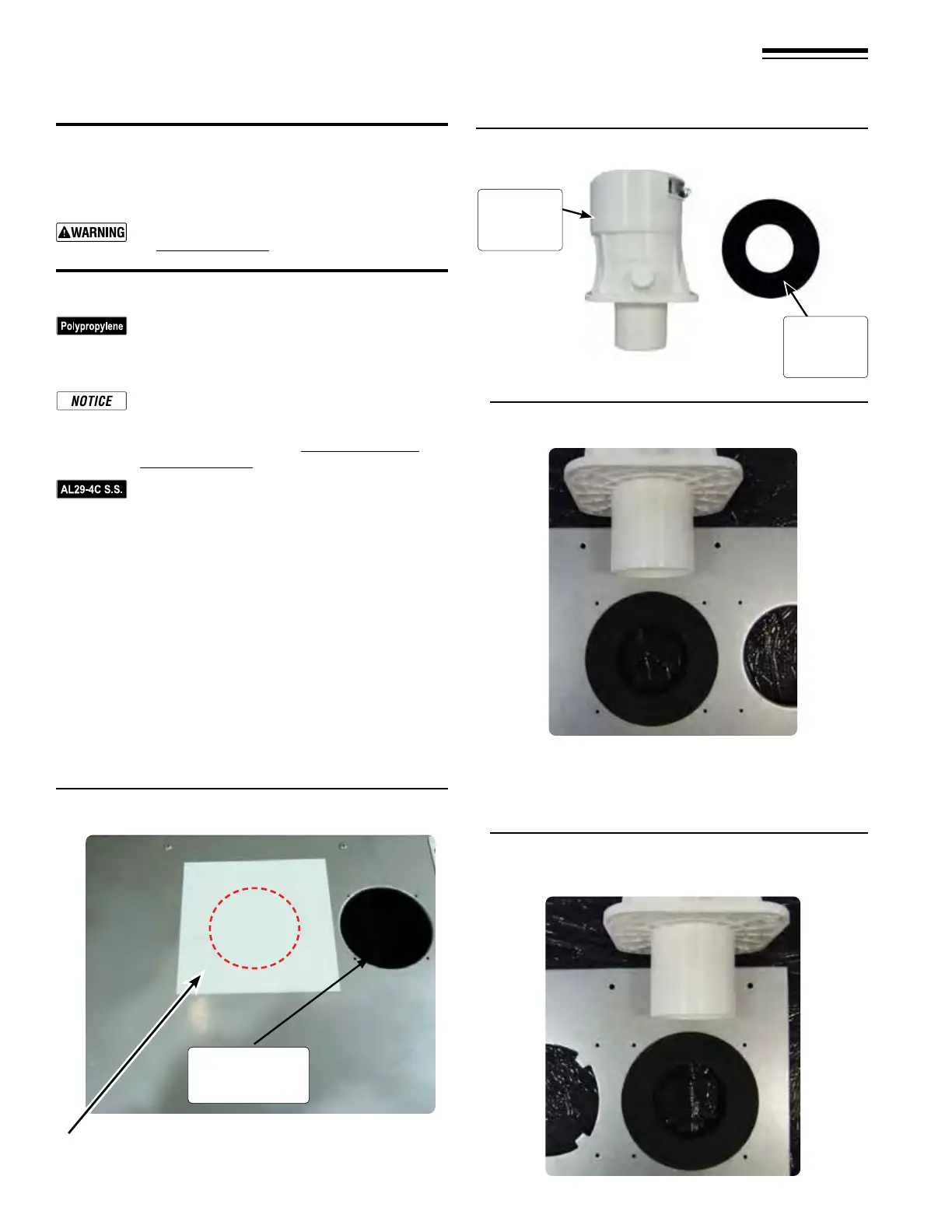
Figure 40 Flue and vent adapter and gasket
5. See Figure41, center ue gasket and insert the extruded ue
vent adapter into the center opening, secure with four (4)
10-32 Phillips head screws.
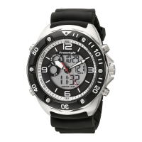
Figure 41 Vent ue adapter into top ue center opening
Remove protective paper.
Figure 42 Vent (air inlet) adapter inserted into top right
opening
Air pipe
connection
vent/exhaust
location
Vent
adapter
Vent
gasket