Part number 550-142-950/0122
56
FreeStyle
®
series
2
wall mount gas-fired water boiler – boiler manual
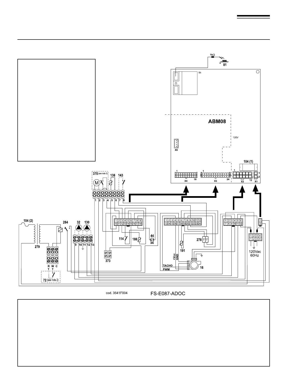
24 Wiring diagram — FS-80/120 Heating Only Ladder
Figure 74 FreeStyle® 80/120 Heating Only Ladder Wiring Diagram
Legend
16 Fan
32 Central heating pump (not included)
44 Gas valve
72 Room thermostat (optional)
81 Ignition electrode
104(1) Fuse 3.15A
104(1) Fuse 630mA
114 Water pressure switch
130 DHW Pump (not included)
138 Outdoor sensor
143 DHW tank thermostat (optional)
186 Return temperature sensor
191 Exhaust temperature sensor
278 Double sensor (heating + safety)
279 Transformer 115-24 VAC
284 Relay SPST-Coil 24 VAC
370 LWCO (not included)
373 “OPENTHERM” communication (Not used)
LN
NOTES:
1. All wiring must be installed in
accordance with N.E.C. and
any other national state or local
requirements.
2. Room thermostat should be a
dry contact type and should draw
power from the control board:
should not be greater than 24
VAC and 500 mA.
3. Terminals 1 & 2 are powered
with 120 VAC for LWCO. Com-
bined current draw for LWCO,
Boiler and DHW Pumps should
not exceed 3 Amps Max.
4. In case of questions during
installation please contact your
local W-T Tech Services.