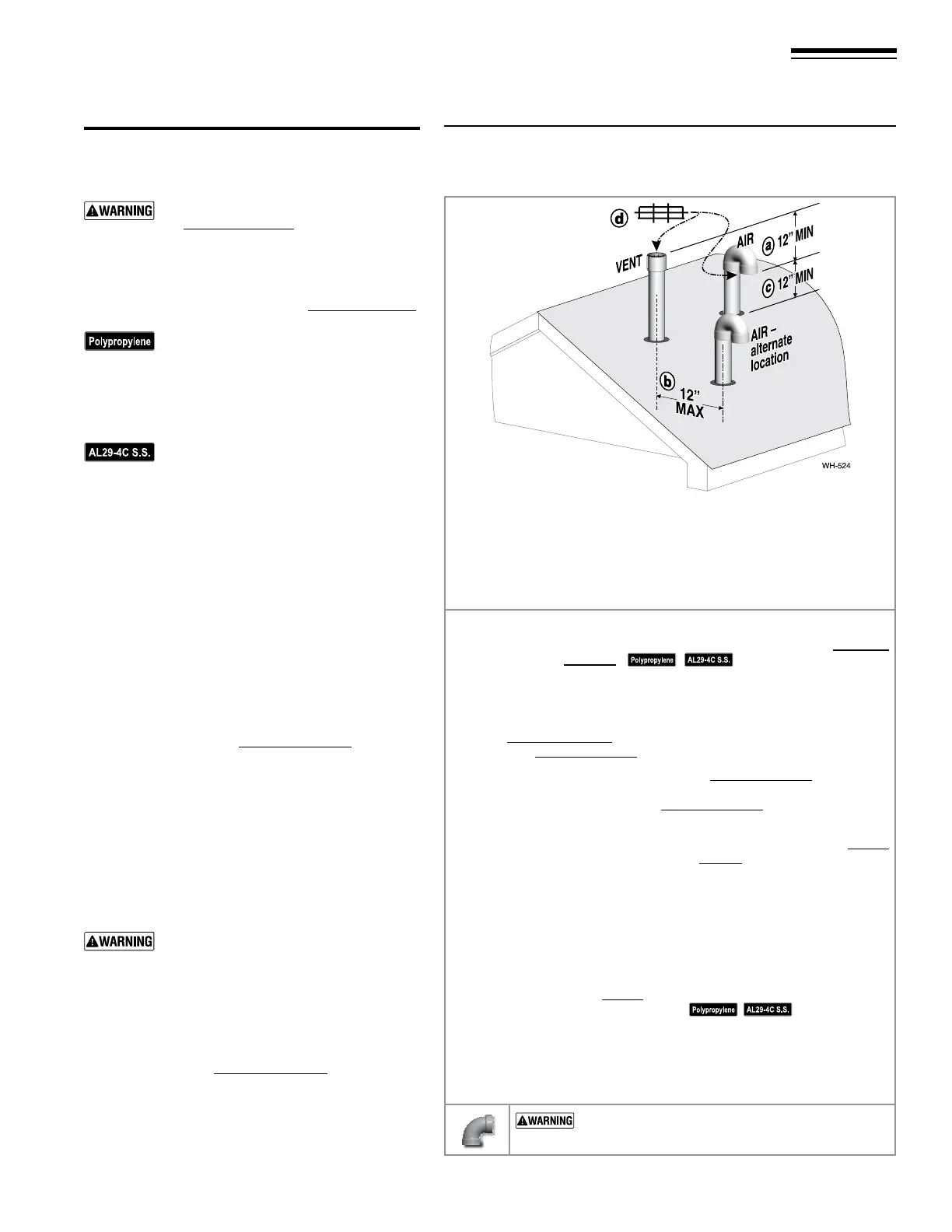
Figure 30 Separate pipes vertical termination
Terminate vent and air pipes such that:
a. AIR INTAKE IS AT LEAST 12 inches below vent outlet
b. AIR INTAKE IS NO FURTHER than 12 inches away center to center
c. AIR INTAKE IS AT LEAST 12 inches above roof or snow line,
keep vents/air intake area clear of accumulating snow.
d. Vent and air terminations are tted with bird screens
Step 1 Read and follow all instructions in this manual. DO NOT proceed
with vent/air installation until you have read page 15
through page 20.
See notices at le.
Step 2 Install the boiler in a location that allows proper routing of all vent
and air piping to the selected sidewall location.
Step 3 Make sure the selected vertical termination location complies with
Figure22,page19. (Multiple boiler terminations must also comply
with Figure31,page26.)
Step 4 Use only the vent materials listed in Figure21,page17. Provide pipe
adapters where required. Vent piping and air piping lengths must not
exceed the values shown in Figure20,page16.
Step 5 Prepare the vertical penetrations and secure penetration components
as instructed in this section. See “Prepare roof penetrations” on page26
and “Termination and ttings” on page26.
Step 6 e air piping must terminate in a 180-degree return bend or down-
turned elbow as shown above. e vent piping must terminate in a
coupling pointed upward as shown above.
Step 7 Install vent and air piping between the boiler and the vertical termina-
tions. Slope horizontal piping downward toward the boiler at least 1/4
inch per foot. Install pipe supports every 5 feet on both the horizontal
and vertical runs. Install a hanger support within 6inches of any upturn
in the piping. See page32 for general guidelines. Also comply with vent
pipe manufacturer’s instructions.
See notices at le.
Step 8 Insert the vent and air piping through the vertical penetrations and
secure the termination ttings.
Step 9 Maintain clearances shown above. Vent and air terminations must be
tted with a bird screen as shown.
USE SWEEP ELBOWS FOR ALL VENT AND AIR
PIPING — DO NOT use short radius elbows for vent or
air piping. Boiler performance could be aected.
Part number 550-142-950/0122
25
FreeStyle
®
series
2
wall mount gas-fired water boiler – boiler manual
Allowable vent/air pipe materials
& lengths
Use only the vent materials and kits listed
in Figure21,page17. Provide pipe adapt-
ers if specied.
Locate the terminations such that the total air piping and
vent piping from the boiler to the termination will not
exceed the maximum length given in Figure20,page16.
For polypropylene applications, comply
with any additional requirements in the
vent system manufacturer’s instructions.
(Do Not use 3”PVC transition pieces
at the boiler vent and air connections).
Install a locking collar at every joint.
For AL29-4C vent pipe applications,
comply with any additional requirements
in the vent system manufacturer’s instruc-
tions. Provide a AL29-4C starter piece
from the AL29-4C manufacturer to the
transition piece at the boiler vent con-
nection. e air piping must be PVC or
CPVC. Provide a 3”PVC transition piece
at the boiler air connection if using 2” air
piping.
Determine termination location
1. e air and vent terminations must be installed as
shown in Figure30.
2. e terminations must comply with clearances and
limitations shown in Figure22,page19.
3. Locate the terminations so they are not likely to be
damaged by foreign objects, such as stones or balls,
or subject to buildup of leaves or sediment.
Multiple vent/air terminations
1. When terminating multiple boilers, terminate each
vent/air connection as described in this manual.
Terminate all vent pipes at the same height
and all air pipes at the same height to avoid
possibility of severe personal injury, death
or substantial property damage.
2. Place roof penetrations to obtain minimum clear-
ance of 12inches between edge of air intake elbow
and adjacent vent pipe of another boiler for U. S.
installations (see Figure33,page28).
3. e air inlet of a FreeStyle® boiler is part of a direct
vent connection. It is not classied as a forced air
intake with regard to spacing from adjacent boiler
vents.
12 DIRECT VENT — Vertical with separate pipes