Part number 550-142-950/0122
33
FreeStyle
®
series
2
wall mount gas-fired water boiler – boiler manual
16 Vent and air piping and boiler connections (continued)
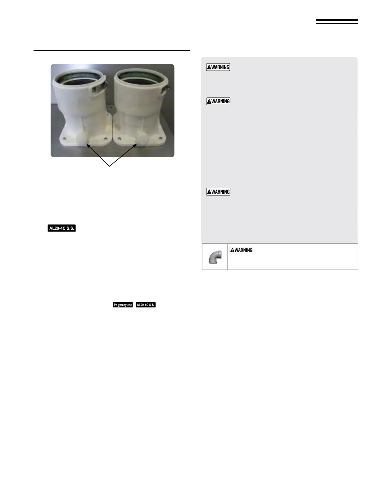
6. See Figure43, right air inlet, center gasket and air inlet vent
adapter over right opening, secure with four (4) 10-32 Phil-
lips head screws.
7. e adapter accepts 3”PVC, CPVC, Polypropylene and
AL29-4C material. Use a 2” adapter, if needed.
For AL29-4C vent pipe applications, comply
with any additional requirements in the vent system manu-
facturer’s instructions. Provide a AL29-4C starter piece from
the AL29-4C manufacturer to the transition at the boiler
vent connection.
8. Cut pipe to required lengths.
9.
Dr
y assemble entire vent or air piping to ensure proper t
before assembling any joint.
10.
M
aintain minimum clearance of
3/16 inch between vent pipe
and any combustible wall or material.
11.
A
ssembling PVC or CPVC: (
— follow pipe
manufacturer’s instructions for preparation and assembly)
a.
D
eburr inside and outside of pipe ends.
b.
C
hamfer outside of each pipe end to ensure even cement
distribution when joining.
c. Clean all pipe ends and ttings. Dry thoroughly.
d. For each joint:
y H
andle ttings and pipes carefully to prevent con-
tamination of surfaces.
y A
pply primer liberally to both joint surfaces — pipe
end and tting socket.
y W
hile primer is still damp, lightly apply approved
cement to both surfaces in a uniform coating.
y Apply a second coat to both surfaces. Avoid using
too much cement on sockets to prevent cement
buildup inside.
y W
ith cement still wet, insert pipe into tting, twisting
¼ turn. Make sure pipe is fully inserted.
y W
ipe excess cement from joint. Check joint to be
sure a smooth bead of cement shows around the
entire joint.
12.
S
eal wall or oor penetration openings following local code
requirements.
ADAPTERS
— Use adapters if using 2-inch pipe.
1. Clean and deburr inside and outside of both ends of air and vent
pipes. Chamfer boiler end of vent pipe for ease of insertion.
e vent pipe end must be smooth and chamfered to
prevent possible damage to sealing gasket in vent pipe
adapter.
2. Inspect vent or air adapter (above) — verify no obstructions or
foreign objects inside.
3. Loosen clamp screw (if used).
4. Measure 2¼-inches from end of pipe and make a mark with felt-
tip pen.
5. Apply small amount of silicon grease to end of pipe to ease insertion.
6. Insert pipe into adapter.
7. Slide pipe down until the 2¼-inch mark is reached.
Do not apply excessive force or bend the adapter or ue/
air pipe when inserting. e adapter or seal could be dam-
aged. If any portion of the vent or air system is damaged,
it must be replaced.
8. e seal is accomplished with the internal gasket.
USE SWEEP ELBOWS FOR ALL VENT
AND AIR PIPING — DO NOT use short radius
elbows for vent or air piping. Boiler performance
could be aected.
Figure 43 Vent (ue) and air adapters in place
Vent and Air adapters to be installed with test ports facing to
front of boiler. Must be locked closed.