Part number 550-142-950/0122
53
FreeStyle
®
series
2
wall mount gas-fired water boiler – boiler manual
• Outdoor sensor uses the back connection block, see Fig-
ure66,page52, Item 138, (right side of block … terminals 5 and
6 ) for the Heating Only boiler.
• Recommended wire size 22 AWG /100” in length (2-conductor
thermostat wire 22 gauge).
• Mount on north exterior wall,
shielded from direct sunlight or
ow of heat or cooling from other sources, approximately 10 feet
above ground level.
• Do NOT run sensor wires with other electrical wires.
The outdoor sensor must be installed unless specical-
ly exempted in the Energy Act statement on page 135.
Figure 68 Outdoor sensor optional for Combi boiler.
22 Field wiring (continued)
Figure 69 Indirect tank aquastat connections
Wiring the Indirect Tank Aquastat
Wiring the indirect tank aquastat to the Heating Only Boiler, will
re the boiler to provide heated boiler water to the indirect tanks
heating coil.
• Field supplied; zone panel, with priority zone, indirect circulator,
zone valve for indirect tank.
• Connect indirect aquastat N/O contact wires to boiler connec-
tions #7 and #8, see Figure69 below.
• Boiler must be in the “comfort mode” (not “eco” mode) push
eco/comfort button to exit “eco” mode, display will Not show
“eco” on display when in correct mode, when using an Indirect
Water Heater Tank.
Wiring the Circulators (Heating Only Boiler)
e control of the Heating Only model of the FreeStyle
boiler is capable of managing two (2) separate circulators,
one for the Heating circuit and one for the Domestic Hot
water circuit.
e connections are located on the rear part of the control
case. In order to access the connector you will have to
unscrew the screw located on the lower right corner of the
control to enable you to rotate the control and access the
connectors. See Figure70 and Figure71.
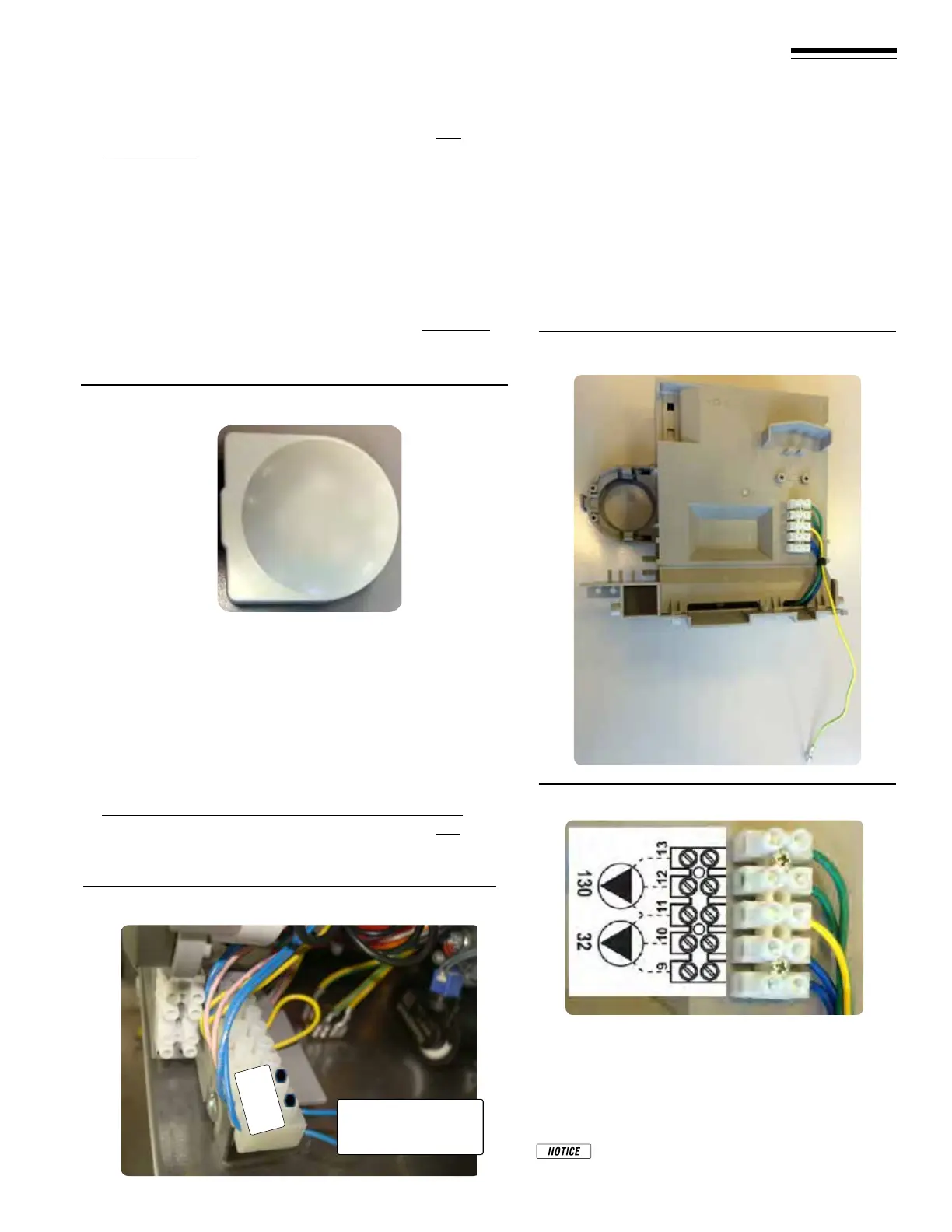
Figure 70 Circulator connectors (Heating Only
boilers)
Figure 71 Circulator connectors detail
In Figure71, terminals 9, 10 and 11 (Item 32) are for con-
necting the Heating circuit circulator.
Terminals 11, 12, and 13 (Item 130) are for connecting the
Domestic Hot water circuit circulator.
e common terminal 11 is ground.
Only one circulator may be wired to each con-
nection point.
Indirect tank aquastat
(N/O) wire connection
points, pins 7 and 8
7
8