Part number 550-142-950/0122
30
FreeStyle
®
series
2
wall mount gas-fired water boiler – boiler manual
14 DIRECT VENT — Vertical vent /sidewall air (continued)
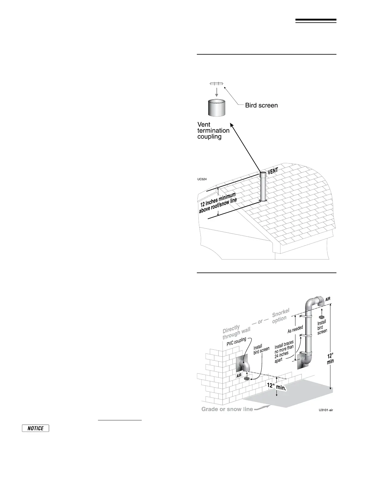
Figure 36 Vent termination (through the roof) for
direct vent: vertical vent / sidewall air
Figure 37 Sidewall air inlet (termination) for direct
vent: vertical vent / sidewall air
Determine location for air inlet elbow
1. e air inlet of an boiler is part of a direct vent connection. It is
not classied as a forced air intake with regard to spacing from
adjacent appliance terminations.
2. Locate the air inlet elbow (termination) using the following
guidelines.
3. e air piping must terminate in a down-turned elbow as shown
in Figure37.
a. Apply the conguration on the le side of Figure37 unless
the terminations would fail to meet minimum clearance to
grade or snow line.
b. Apply the conguration on the right side of Figure37 when
the terminations need to be raised higher to meet clearance
to grade or snow line.
c. e air pipe may run up the side of the building, as shown.
e vent and air pipes must be secured with braces, and all
clearances and lengths must be maintained. Space braces no
further than 24 inches apart.
4. You must consider the surroundings when terminating the air
connection:
a. Make sure there are no obstructions for air ow. DO NOT
locate the termination where plants could grow and cause
obstruction to air ow.
b. Do not locate the terminations where wind eddies could af-
fect performance or cause recirculation with exhaust from
other appliances, such as inside building corners, near adja-
cent buildings or surfaces, window wells, stairwells, alcoves,
courtyards or other recessed areas.
c. Locate the air inlet termination at least 12 inches below and 12
inches horizontally from any appliance or building vent outlet.
5. Locate terminations so they are not likely to be damaged by
foreign objects, such as stones or balls, or subject to buildup of
leaves or sediment.
Multiple air terminations
1. When terminating multiple boiler air connections, terminate each
air connection as described in this manual.
2. Place wall penetrations to obtain minimum clearances as in-
structed in this manual.
3. Place adjacent air inlets for multiple boilers at least 6inches apart.
4. Combustion air (NOT vent piping) can be manifolded.
Prepare wall penetrations
1. Air pipe penetration:
a. Cut a hole for the air pipe. Size the air pipe hole as close as
desired to the air pipe outside diameter.
2. Seal exterior openings thoroughly with exterior caulk.
Termination and ttings
1. Prepare the air termination elbow (Figure37) by inserting a bird
screen. Bird screens must be purchased separately. See the parts
list at the end of this manual for part numbers.
2. Use metal plates (by installer) at inside and outside penetrations
using the method shown in Figure26,page22.
If extending the air pipe out from the wall, install a cou-
pling on each pipe. Mount the piping with the coupling
ush with the outer plate.