Figure 25
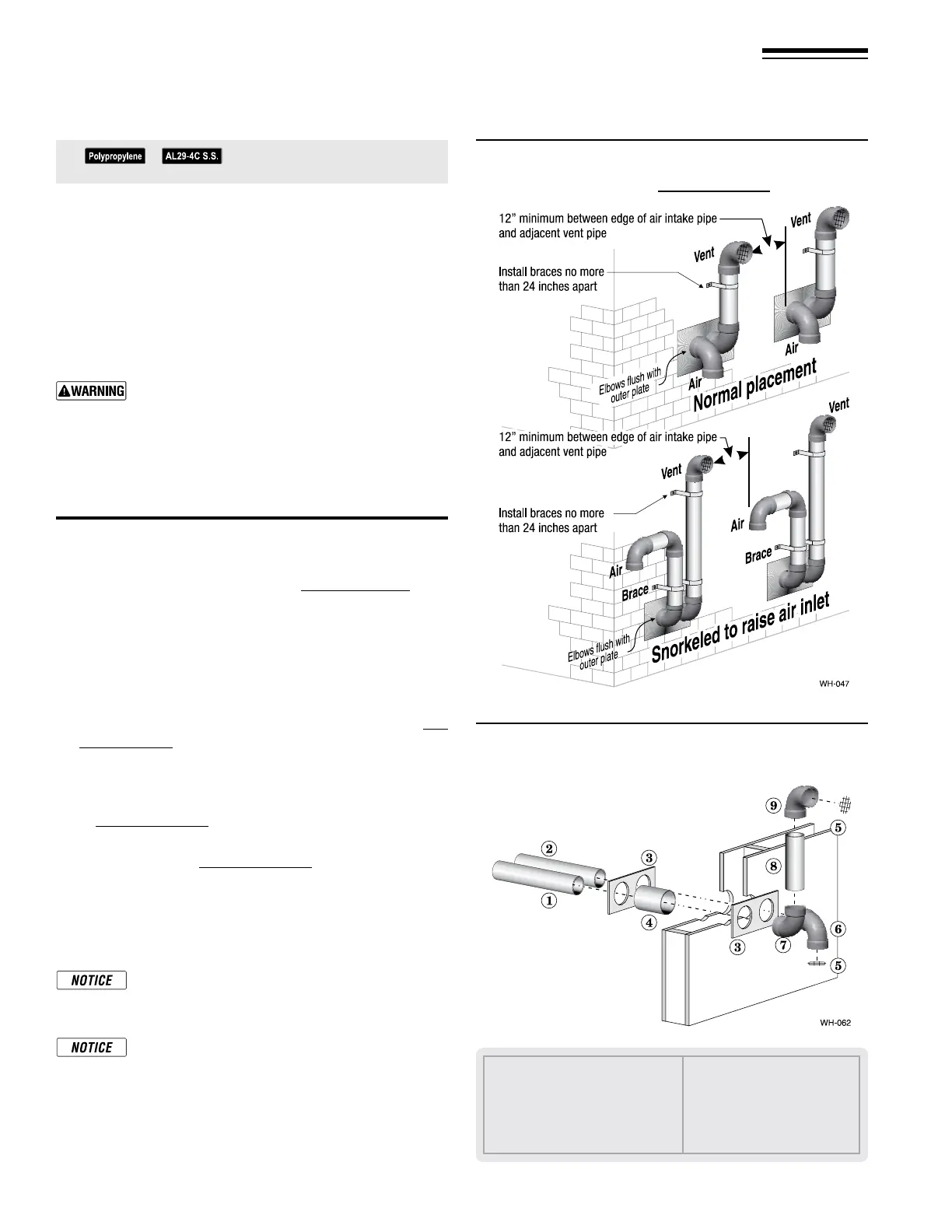
Multiple separate pipes sidewall terminations —
maintain vertical spacing between vent and air
ttings shown in Figure 24, page 21.
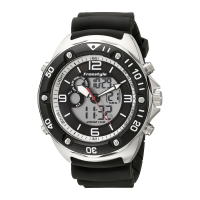
Figure 26 Sidewall termination assembly — using
separate pipes
See notices on previous page.
Part number 550-142-950/0122
22
FreeStyle
®
series
2
wall mount gas-fired water boiler – boiler manual
10 DIRECT VENT — Sidewall with separate pipes continued
a. Cut a hole for the vent pipe. For either combustible or
noncombustible construction, size the vent pipe hole at
least 0.4” larger than the vent pipe diameter.
b. Insert a galvanized metal thimble in the vent pipe hole
as shown in Figure26.
c. Plate may be eld fabricated from corrosion resistant
material of sucient strength. Plate must allow venting
to maintain minimum clearance to combustibles.
Ensure that the plate material is strong enough to
prevent the termination from being pushed inward
if struck or pushed from the outside.
1. Follow all local codes for isolation of vent pipe when passing
through oors or walls.
2. Seal exterior openings thoroughly with exterior caulk.
Termination and ttings
1. Prepare the vent termination elbow and the air termination
elbow by inserting bird screens. (See Figure24,page21.) Bird
screens must be purchased separately. See the parts list at the
end of this manual for part numbers.
2. Secure the elbows so they will butt against the sidewall ter-
mination plate.
3. When completed, the air termination coupling must be
oriented at least 12 inches below the vent termination and
at least 12 inches above grade or snow line as shown in Fig-
ure24,page21.
Keep vents/air intake area clear of accumulating
snow.
4. You can orient the vent termination elbow either directly
outward or 90 degrees away from the air inlet elbow as shown
in Figure24,page21.
5. Maintain the required dimensions of the nished termination
piping as shown in Figure24,page21.
6. For multiple boiler terminations, see Figure25.
7. Do not extend exposed vent pipe outside of building more
than shown in this document. Condensate could freeze and
block vent pipe.
If extending the vent and air pipes out from the wall,
install a coupling on each pipe. Mount the piping
with the coupling ush with the outer plate.
Wall penetration thickness between 2” to 24”.
1 Vent piping
2 Air piping
3 Sidewall termination plates: for 3”PVC
or 3” AL29-4C or 2” PVC, (eld supplied)
4 Galvanized thimbles, by installer
5 Bird screen, by installer
6 Air inlet elbow
7 Elbow
8 Nipple
9 Vent termination elbow