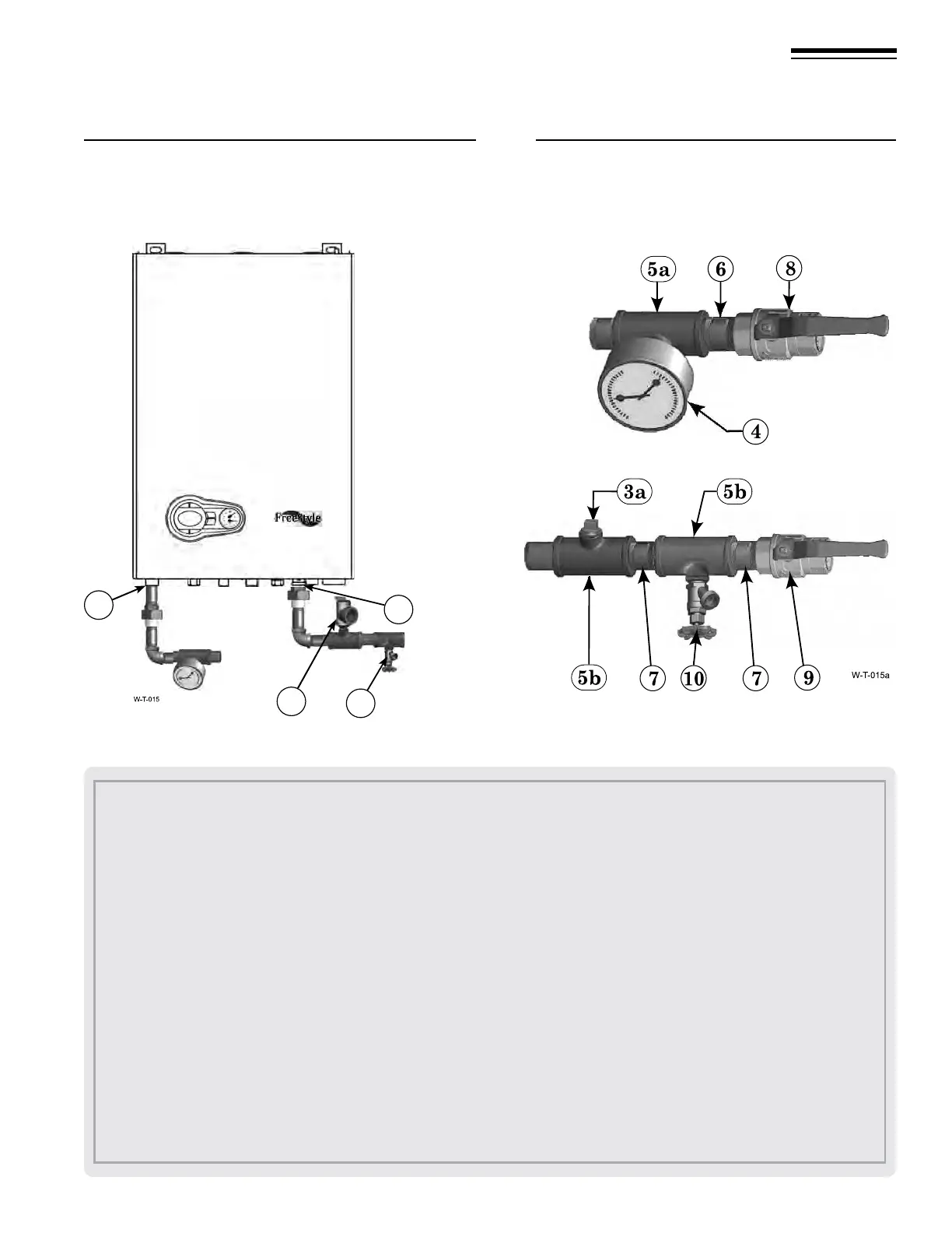
Figure 5 Install pipe ttings for relief valve and pressure/
temperature gauge —
DO NOT mount relief
valve until AFTER hydrostatic testing
(see
legend below) (Combi boiler shown)
Figure 6 Install piping components required for
hydrostatic test (
see legend below)
Part number 550-142-950/0122
9
FreeStyle
®
series
2
wall mount gas-fired water boiler – boiler manual
1. Boiler supply (outlet) connection, (male, 1” NPT on FS-80/120, 1” NPT on FS-155).
2. Boiler return (inlet) connection, (male, 1” NPT on FS-80/120, 1” NPT on FS-155).
Recommend Near Boiler Piping to be 1-1/4” NPT or larger for FS-155. Bushing 1” x 1-1/4” NPT at Supply (outlet) and Return (inlet)
not shown. (eld supplied
by installer)
3. Boiler relief valve, shipped loose with boiler — DO NOT mount relief valve until AFTER hydrostatic testing.
3a.
TEMPORARIL
Y ONLY — Insert a ¾” NPT plug in the relief valve tapping of the reducing tee. This MUST BE REMOVED
after the test and the relief valve mounted here.
4.
P
ressure/temperature gauge,
(eld supplied) by installer
5a.
Re
ducing tee, NPT, 1” x 1” x ¼” on FS-80/120, NPT, 1-¼” x 1-¼” x ¼” on FS-155.
5b. Tee, NPT, 1” x 1” x ¾” on FS-80/120, NPT, 1-¼” x 1-¼” x ¾” on FS-155.
6.
N
ipple, NPT 1”x close on FS-80/120, NPT, 1-¼” x close on FS-155,
(eld supplied) by installer.
7.
N
ipple, NPT 1”x close on FS-80/120, NPT, 1-¼” x close on FS-155,
(eld supplied) by installer.
8.
I
solation valve on supply connection,
(eld supplied) by installer (1”NPT on FS-80/120, 1-¼”NPT on FS-155).
9. Isolation valve on return connection, (eld supplied) by installer (1”NPT on FS-80/120, 1-¼”NPT on FS-155).
10. ¾” NPT boiler drain valve, (eld supplied) by installer — aer hydrostatic testing, move drain valve to lowest point on the return
piping if not already there.
3 Prepare boiler continued
2
1
Boiler Return
(inlet)
Boiler Supply
(outlet)
3
10