Figure 6 )NSTALLPIPElTTINGSFORRELIEFVALVEANDPRESSURE
TEMPERATUREGAUGE
$/./4MOUNTRELIEF
VALVEUNTIL!&4%2HYDROSTATICTESTING
(see
legend below)
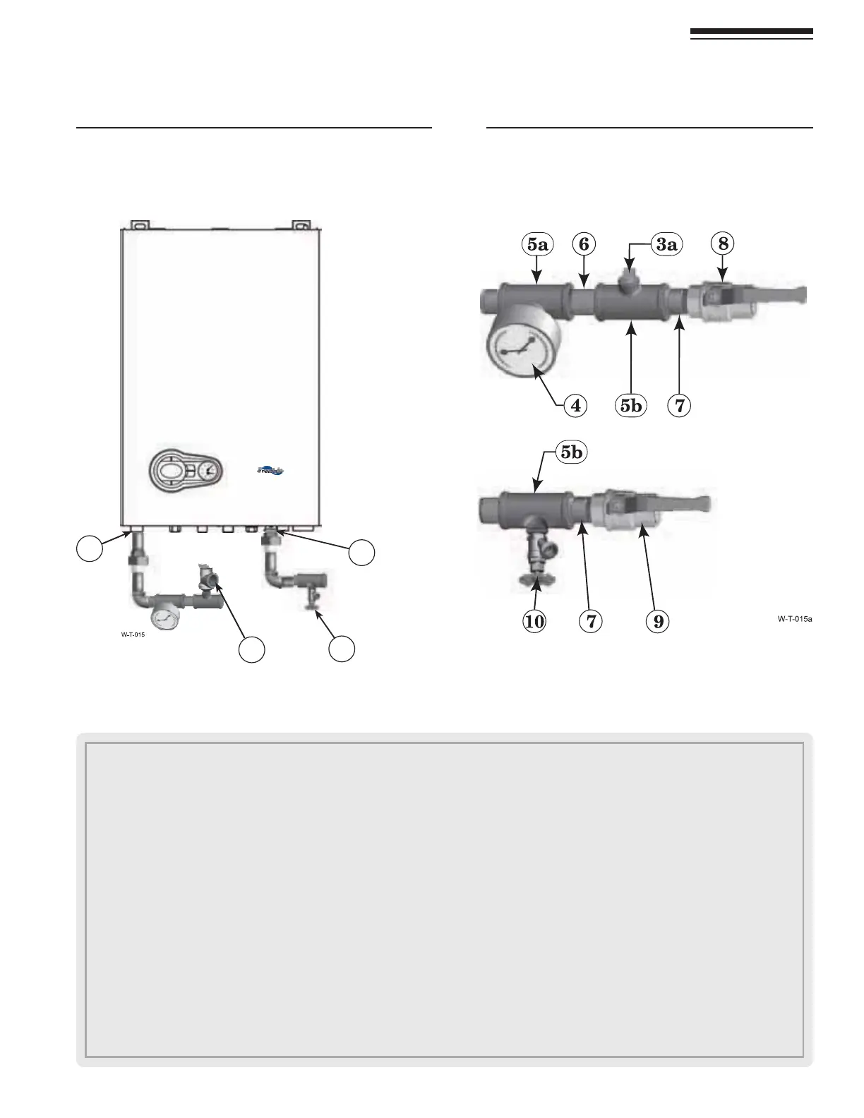
&IGURE )NSTALLPIPINGCOMPONENTSREQUIREDFOR
HYDROSTATICTEST
see legend below)
Part number 550-142-850/0716
11
FreeStyle
®
WALL MOUNT GAS-FIRED WATER BOILER — Boiler Manual
1. Boiler supply (outlet) connection, (male, ¾” NPT on FS-80/120, 1”NPT on FS-155).
2. Boiler return (inlet) connection, (male, ¾” NPT on FS-80/120, 1”NPT on FS-155).
3. Boiler relief valve, shipped loose with boiler — $/./4MOUNTRELIEFVALVEUNTIL!&4%2HYDROSTATICTESTING.
3a. 4%-0/2!2),9/.,9 Insert a ¾” NPT plug in the relief valve tapping of the reducing tee. 4HIS-534"%2%-/6%$
after the test and the relief valve mounted here.
4. Pressure/temperature gauge,
(field supplied) by installer
5a. Reducing tee, NPT, ¾ ” x ¾” x ¼” on FS-80/120, NPT, 1 ” x 1” x ¼” on FS-155.
5b. Tee, NPT, ¾ ” x ¾ ” x ¾” on FS-80/120, NPT, 1 ” x 1” x ¾” on FS-155.
6. Nipple, NPT ¾” x close on FS-80/120, NPT, 1 ” x close on FS-155,
(field supplied) by installer
7. Nipple, NPT ¾” x close on FS-80/120, 1 ” x close on FS-155,
(field supplied) by installer
8. Isolation valve on supply connection,
(field supplied) by installer (¾” NPT on FS-80/120, 1”NPT on FS-155).
9. Isolation valve on return connection, (field supplied) by installer (¾” NPT on FS-80/120, 1”NPT on FS-155).
10. ¾” NPT boiler drain valve, (field supplied) by installer — after hydrostatic testing, move drain valve to lowest point on the return piping
if not already there.
3 Prepare boiler continued
0IPINGFROMSYSTEM
0IPINGTOSYSTEM
2
3
1
10