070.750-IOM2 (JUN 22)
Page 12
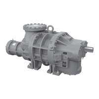
HPS 273 and 407 Rotary Screw Compressor
Installation
Foundation
Each HPS Rotary Screw Compressor is shipped mounted
on a wooden skid. Remove before installing the unit.
Caution
Allow correct spacing for servicing. See the relevant
dimensional outline drawing.
The rst requirement of the compressor foundation is that
it must be able to support the weight. The weights of the
HPS 2709 and HPS 2712 assemblies respectively are 2,132
kg (4,700 lb) and 2,241 kg (4,940 lb). The weights of the
HPS 4009 and HPS 4012 compressor models respectively
are 5,185 kg (11,432 lb) and 5,519 kg (12,167 lb).
Screw compressors are capable of converting large quan-
tities of shaft power into gas compression in a relatively
small space. The compression process creates relatively
high frequency vibrations that require sufcient mass
in the base to effectively dampen them. Refer to FRICK
070.210-IB, Screw Compressor Foundations.
The best insurance for a trouble-free installation is to
rmly anchor the compressor to a suitable foundation
using correct bolting and by preventing piping stress from
being imposed on the compressor. After rigging the com-
pressor into place, you must shim its feet to level it. There
must be absolutely no stresses transferred to the com-
pressor body due to bolting of the feet and anges.
In any screw compressor installation, support suction and
discharge lines in pipe hangers, preferably within 2 ft (0.61
m) of vertical pipe run, so that the lines won’t move if dis-
connected from the compressor. See Table 8 for allowable
ange loads.
Motor mounting, for foot-mounted
motor only
1. Thoroughly clean the motor feet and mounting pads of
grease, burrs, and other foreign matter to ensure rm
seating of the motor.
2. Attach the motor to the base using bolts and motor
raising blocks, if required.
3. Weld the four kick bolts into place so that they are
positioned to allow movement of the motor feet. The
kick bolts are not included with compressor.
4. After setting the motor, check to see that the shafts
are correctly spaced for the coupling being used. Check
the appropriate dimensional outline drawing for the
minimum clearance required between the shaft ends to
change the shaft seal.
Compressor/motor coupling requirements
HPS compressors are arranged for direct motor drive and
require a exible drive coupling to connect the compressor
to the motor. Coupling must be suitable for variable speed.
The HPS 273 and 407 models use a keyless drive shaft.
For a foot-mounted motor, it is essential to correctly align
the coupling to ensure correct bearing and seal perfor-
mance:
1. Select and install the coupling so that it does not trans-
mit any axial load to the compressor shaft.
2. Set up the minimum distance between the compressor
shaft and motor shaft to enable seal removal. See the
relevant outline drawings.
3.
Coupling must be able to take up any misalignment
between the motor and compressor. It is critical to the
life of the shaft seal that misalignment is kept to the
minimum possible value. Follow the coupling manu-
facturer’s guidelines for checking and correcting any
misalignment.
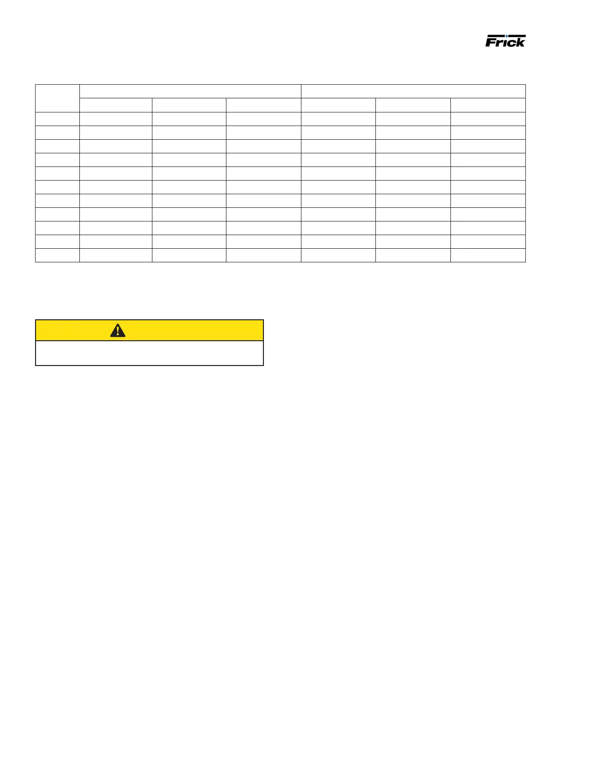
Table 8: Allowable ange loads
Nozzle
size NPS
Moments, ft-lbf (N
.
m) Load, lbf (N)
Axial - M
R
Vert. - M
C
Lat. - M
L
Axial - P Vert. - V
C
Lat. - V
L
1 25 (34) 25 (34) 25 (34) 50 (222) 50 (222) 50 (222)
1.25 25 (34)
25 (34) 25 (34) 50 (222) 50 (222) 50 (222)
1.5 50 (68) 40 (54) 40 (54) 100 (445) 75 (334) 75 (334)
2 100 (136) 70 (95) 70 (95) 150 (667) 125 (556) 125 (556)
3 250 (339) 175 (237) 175 (237) 225 (1,001) 250 (1,112) 250 (1,112)
4 400 (542) 200 (271) 200 (271) 300 (1,334) 400 (1,779) 400 (1,779)
5 425 (576) 400 (542) 400 (542) 400 (1,779) 450 (2,002) 450 (2,002)
6 1,000 (1,356) 750 (1,017) 750 (1,017) 650 (2,891) 650 (2,891) 650 (2,891)
8 1,500 (2,034) 1,000 (1,356) 1,000 (1,356) 1,500 (6,672) 900 (4,003) 900 (4,003)
10 1,500 (2,034) 1,200 (1,627) 1,200 (1,627) 1,500 (6,672) 1,200 (5,338) 1,200 (5,338)
14 2,000 (2,712) 1,800 (2,440) 1,800 (2,440) 1,700 (7,562) 2,000 (8,896) 2,000 (8,896)