070.750-IOM2 (JUN 22)
Page 6
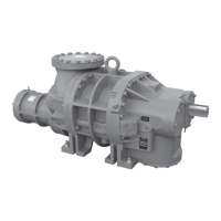
HPS 273 and 407 Rotary Screw Compressor
Installation - Operation - Maintenance
Maintaining the compressor in storage
1. Maintain the 0.3 bar to 1.0 bar (4.35 psig to 14.5 psig)
nitrogen charge, but ideally at 1.0 bar (14.5 psig).
2. Rotate the male rotor shaft monthly. Mark the shaft to
ensure the rotor does not return to the original posi-
tion.
3. Store the compressor inside a dry building environ-
ment.
4. Grease the male rotor shaft to prevent rust.
5. Record all information in a compressor long-term
storage log. See Table 1.
Contact Johnson Controls-Frick Service with any questions
regarding long-term storage.
Description
HPS 273 and 407 compressors
The Frick HPS 273 and 407 rotary screw compressors
use mating asymmetrical prole helical rotors to provide
a continuous ow of vapor and are designed for high-
pressure applications. The compressor incorporates the
following features:
• Designed for variable speed drive (VSD) with a range of
600 rpm to 4,200 rpm for the HPS 273 and 3,600 rpm
for the HPS 407. It is also possible to operate with a
xed-speed motor drive at 2,950 rpm or 3,550 rpm or a
xed-speed engine drive at 1,200 rpm.
• The HPS 273 and 407 compressor models use stepless
capacity control providing innite unloading capacity
down to about 20% of full-load capacity.
• The HPS 273 and 407 compressor models have a
moveable slide stop with three Vi ranges offered as
standard:
– 2.2 Vi to 5.0 Vi
– 1.7 Vi to 3.0 Vi
– 1.3 Vi to 1.96 Vi
• High capacity roller bearings to carry radial loads are
used at both inlet and outlet ends of the compressor.
• The high pressure compressor models use heavy duty
four-point ball bearings to carry the axial loads on the
rotor for the HPS 273 and 407 compressor models.
• The high-pressure compressor models use balance
piston assemblies to limit the axial bearing loads. HPS
273 and 407 compressor models use one at the male
and female inlet ends that require pressure regulation
on the oil supply.
• The housings for the HPS 273 and 407 compressor
models are designed for 90 bar (1,300 psig) working
pressure.
• The HPS 273 and 407 compressor models are designed
with multiple ports. See Figure 11 and Figure 12.
• All bearing and control oil is vented to lower pressure
locations inside the compressor, enabling operation
without an oil pump for most applications.
• The shaft seal is designed with a seal ring made of
silicon carbide mated against a similar material, with
carbon and graphite added to the matrix to help
improve startup performance.
The shaft seal housing is designed to maintain operat-
ing pressure on the seal much lower than discharge
pressure for increased seal life.
• Oil injected into the compressor is directed between
the rotor threads to maintain good volumetric and
adiabatic efciency.
• The shaft rotation is clockwise when facing the com-
pressor drive end and is suitable for all types of drives.
Warning
Compressor rotation is clockwise when facing the
compressor drive shaft. Never operate the compressor
in reverse rotation because this can result in damage.
• The suction and discharge anges are ANSI B16.1 Class
600 type for the HPS 273 and 407 compressor models.
System and package piping that connects to the com-
pressor with a matching ange must comply with the
applicable piping code requirements based on design
pressure and temperature of the mating component.
• Suction strainers for the HPS 273 and 407 models are
external to the compressor. The strainer specied must
meet the following requirements at a minimum:
– Filter cloth: SS 304, 30 x 150 mesh, plain Dutch
Weave with 0.009 in. WARP diameter and 0.007 in.
WEFT diameter
– Filter cloth support: 6 mesh with 0.035 in. wire di-
ameter, 0.132 in. openings with 62.7% open area
Compressor lubrication system
The lubrication system on a HPS 273 and 407 compressor
unit performs several functions:
• Provides lubrication to bearings, seal, and rotors
• Provides a cushion between the rotors to minimize
noise and vibrations
• Helps keep the compressor at the correct temperature
and prevents overheating
• Provides oil supply to hydraulically operate the slide
valve and slide stop for the HPS 273 and 407 to provide
capacity and volume control
• Provides oil pressure to the balance piston assemblies
to help increase bearing life
• Provides an oil seal between the rotors to prevent ro-
tor contact or gas bypassing