070.750-IOM2 (JUN 22)
Page 28
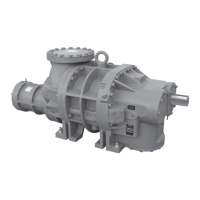
HPS 273 and 407 Rotary Screw Compressor
Forms
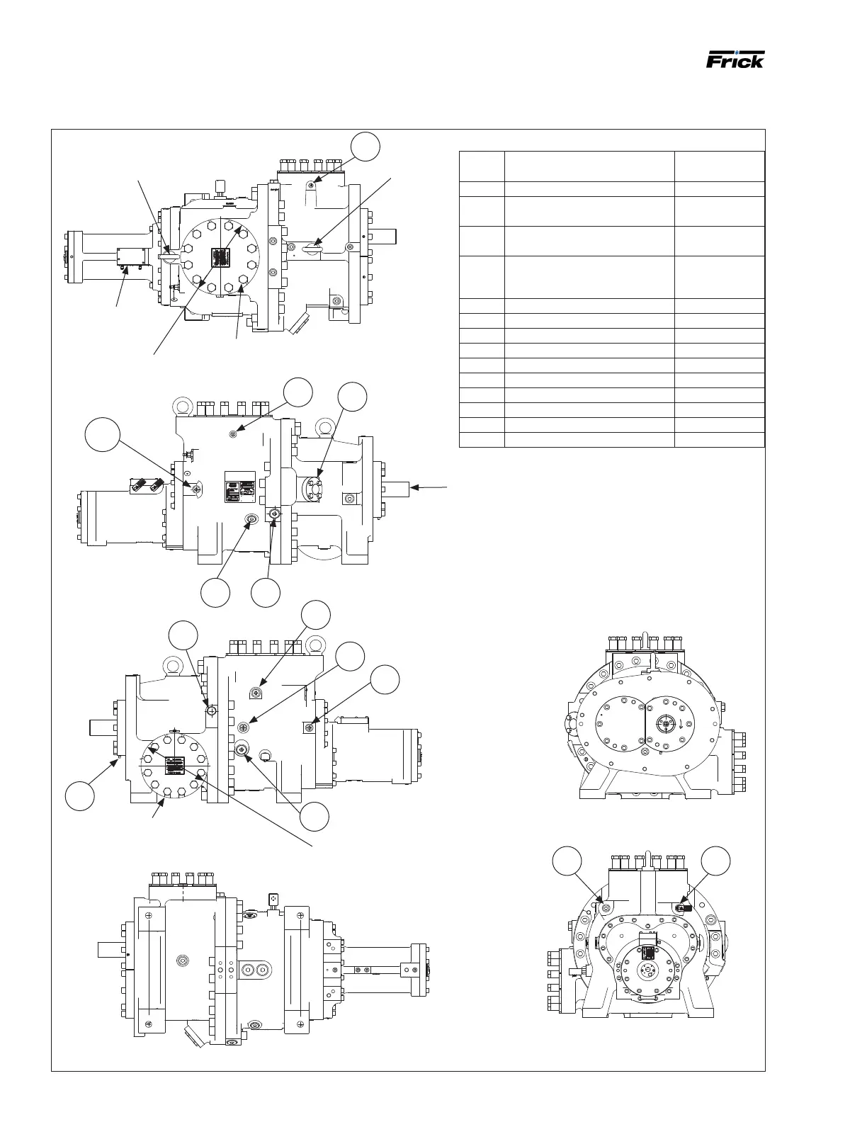
Table 10: 273 connection legend
Port
label
Description Connection
size
P Manifold block pressure 1 1/16-12UN-2B
SB-2 Male and female balance piston
oil feed
1 1/16-12UN-2B
SB-2A Male and female inlet bearing
oil feed
1 1/16-12UN-2B
SB-3 Discharge end bearings, shaft
seal, and manifold block oil feed
1 5/16-12UN-2B
SC-5 Suction pressure 9/16-18UNF-2B
SC-6 Discharge pressure 9/16-18UNF-2B
SC-7 Seal weepage 1/8-27 NPTF
SC-8 Closed thread drain 1 5/16-12UN-2B
SD-1 Coalescer bleed 1 1/16-12UN-2B
SL-0 Liquid injection 1 5/16-12UN-2B
SM-1 Main oil injection, high Vi 1 5/8-12UN-2B
SM-2 Main oil injection, low Vi 1 5/8-12UN-2B
SV-1 Class 600 ANSI round ange 1 1/4 Flange
T Manifold block tank 1 1/16-12UN-2B
Figure 11: Compressor port locations, HPS 2709/2712
SC-6
SC-5
SV-1
SC-8
SL-0
SB-3
SD-1
SB-2
SC-7
SM-2
P T
SM-1
SB-2A
M30 x 3.5 lifting eye
Pad for manifold
block mounting
No keyway in shaft
M30 x 3.5 lifting eye
Ø419.1 [Ø16.50]
Compressor suction ange
(8 in. class 600 ANSI ange)
Ø355.6 [14.00]
Compressor discharge ange,
6 in. Class 600 ANSI ange
5/8-11 UNC - 2B
x 1.31 in. threaded
holes are provided
for ange bolting
1 1/8-7 UNC - 2B x 2 1/2 in. threaded
holes are provided for ange bolting.
4 in. long HEX HD screws are provided
1-8 UNC - 2B X 2 1/2 in. threaded
holes are provided for ange bolting.
3 1/2 in. long HEX HD screws are
provided
Compressor port locations