070.750-IOM2 (JUN 22)
Page 24
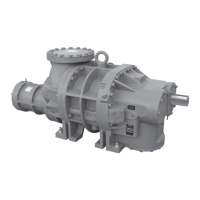
HPS 273 and 407 Rotary Screw Compressor
Maintenance
Troubleshooting the HPS 273 and
407 compressors
Notice
Unless the service technician has been certied by
Johnson Controls–Frick to rebuild our compressors,
troubleshooting the compressor is limited to identi-
fying the probable cause. If a mechanical problem is
suspected, contact Johnson Controls–Frick Service.
Do not attempt to disassemble compressor.
Replacing the capacity linear transmitter: slide
valve
The capacity linear transmitter is located on the end of the
compressor cylinder. See Figure 10. The linear transmit-
ter with hermetic enclosure is based on the inductive
measuring principle. It features removable electronics,
from the sensor well, eliminating the need to evacuate the
compressor for replacement. This type of transmitter is
dedicated to capacity control and is not adjustable.
1. Shut off control power.
2. Remove the DIN connector plug from the transmitter.
3. Loosen the cap screws.
4. Remove the transmitter unit.
5. Install the new transmitter unit.
6. Tighten the cap screws.
7. Apply the DIN connector plug to the transmitter.
8. Turn on control power.
9. Only calibrate using the controller.
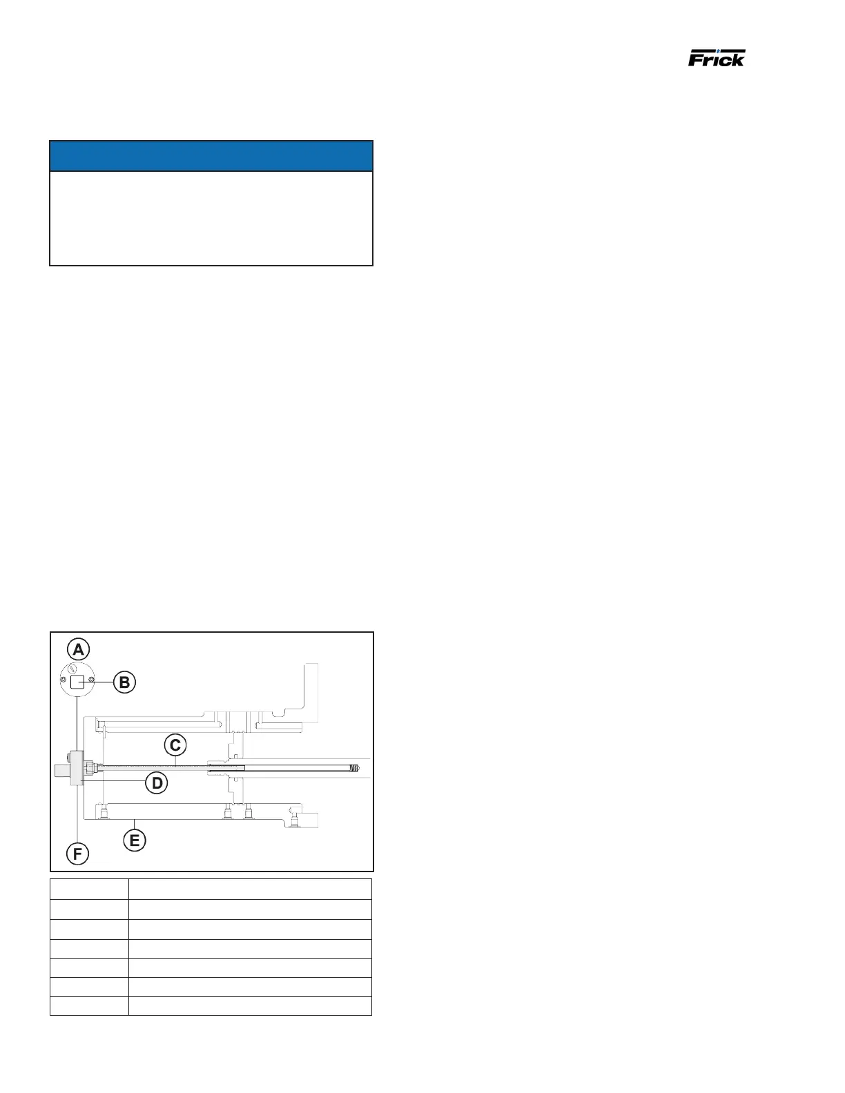
Figure 10: Capacity linear transmitter
Callout Description
A End view
B DIN connector
C Stainless steel well
D Heat isolator
E Compressor unload cylinder
F Cast aluminum housing
Note: Shaded area shows capacity linear transmitter.
Replacing a bare compressor
Only complete following procedure when replacing a bare
compressor in the eld:
1. Verify that main power to the unit is disconnected and
tag the switch.
2. Remove all tubing, piping, and wiring that is connects
to the compressor.
3. Disconnect the coupling from the motor shaft.
4. While supporting the motor and compressor assembly
with a crane, remove the bolts at the motor feet, and
then at the compressor feet.
5. Thoroughly clean the compressor and motor feet and
mounting pads of burrs and other foreign matter to
ensure rm seating of the compressor.
6. Thoroughly clean the new compressor and remove all
cover plates and protection.
7. Install new gaskets and sealing in all connections.
8. Set the new compressor in place and shim feet where
required.
9. Reattach the drive coupling.
10. Check the shaft alignment if a factory-provided motor
mount is not used.
11. Complete tubing, piping, and wiring.
Note: Refer to 070.660-SM, Bare Rotary Screw Compres-
sor Replacement when a motor tunnel is installed.
Shutdown due to incorrect oil pressure, high
stage and booster
The compressor must not operate with incorrect oil pres-
sure.
Refer to relevant Control Setup.