070.750-IOM2 (JUN 22)
Page 8
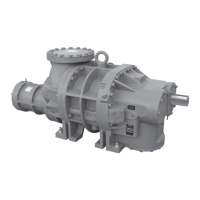
HPS 273 and 407 Rotary Screw Compressor
Installation - Operation - Maintenance
Construction details
Housing
All HPS 273 and 407 screw compressors castings are
60-40-18 ductile iron to ensure structural integrity and me-
chanical and thermal stability under all operating conditions.
Rotors
The rotors are made from quality, wear-resistant rolled
steel to the exacting tolerances of the latest industry stan-
dard asymmetric prole. The six-lobed male rotor directly
connects to the driver. The eight-lobed female rotor is
driven by the male on a thin oil lm.
Bearings
HPS compressors are designed for optimal bearing life.
The HPS 273 and 407 compressor models are designed
with a conventional single-radial bearing design (HPSS). A
double-radial bearing arrangement (HPSD) is available as
an option to handle higher discharge pressure applications.
When evaluating operating conditions of the compres-
sor in CoolWare for performance, give consideration to
changes in those conditions based on operating transients
and seasonal changes. CoolWare automatically congures
the bearing arrangement for optimal life based on these
conditions.
Balance piston
The high pressure compressors are equipped with balance
piston assemblies to reduce load on the axial bearings. Oil
pressure is regulated by a xed or modulating pressure
regulating valve and provides the force necessary to offset
the bearing loads. The pressure setting on the balance
piston pressure regulating valve is important and specied
by Coolware for the specic operating conditions of the
compressor.
Shaft seal
The compressor shaft seal is a single-face balanced type
with a spring-loaded, silicon carbide stationary hardened
surface riding against a rotating seat. Carbon and graph-
ite are added to both surfaces to provide self-lubrication.
During operation, it is vented to low pressure to provide
extended life.
Motor mount
The HPS 273 and 407 series compressors is a foot
mounted, open drive model that can pair with an electric,
engine, or turbine drive.
Design limits
Use CoolWare to determine the limits for a specic
application.
• Maximum suction pressures for the HPS compressors
are limited based on compressor Vi, to avoid over-
compression:
– For A model 2.2 Vi to 5.0 Vi the limit is 27.5 bar
(450 psia)
– For B model 1.7 Vi to 3.0 Vi the limit is 44.8 bar
(650 psia)
– For C model 1.3 to 1.96 Vi the limit is 63.7 bar
(925 psia)
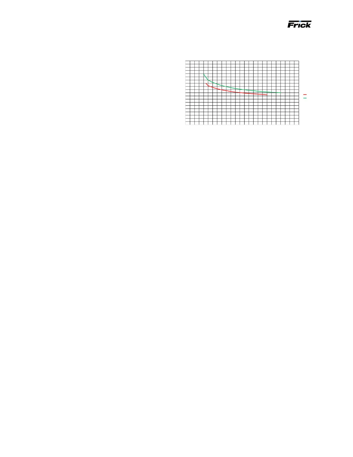
Figure 5: HPS 273 and 407 viscosity requirement as
function of speed
• The maximum discharge temperature for the HPS 273
407 compressor models is limited to 125°C (257°F).
Refer to 160.802-SPC, Compressor Oil Specications
for more detail.
• Screw compressors are oil-ooded machines that use
oil to lubricate bearings, seals, and rotors, and also
to seal clearances in the rotor mesh and control the
compressor’s discharge temperature. Screw compres-
sors however, are designed to compress gases and not
pump liquids, so the amount of oil introduced into the
compressor is regulated. When using variable-speed
motors to drive the compressors, take particular care
to regulate the main oil injection oil ow when slowing
down the driver speed. This is to avoid supplying too
much oil to the compressor, which can result in a failure
due to liquid slugging. If the total oil ow supply to the
compressor is more than 1.5% of the compressor’s
swept volume, and the turndown of the variable-speed
drive is more than 3, the main oil ow must be regulat-
ed. The turndown of a variable-speed drive is dened as
the actual maximum speed of the driver divided by the
actual minimum speed of the driver. CoolWare calculates
the oil ow in Lpm and gpm. See Table 2, Table 3, Table
4, or Table 5 depending on what model you own.
• The UNISAB and Quantum panels have several lay-
ers of control functions to secure reliable operation.
Depending on many operating conditions, they unload
the slide valve and reduce or increase speed to keep
the compressor running in a safe way. Only as a last
resort do they initiate an alarm and ultimately stop the
compressor.
This is particularly true for the HPS 273 and 407
compressor models on applications with high suction
pressure, like fuel gas boosting. The concern is that
the high internal thread pressure may lead to excessive
rotor deection and unwanted contact with the rotor
housing. For this reason,
correct
calibration of the slide
valve and slide stop is essential.
Note: For 1.3 to 1.96 and 1.7 to 3.0 Vi range machines, the
main oil injection occurs at lower Vi port locations
than compressors operating with the 2.2 to 5.0 Vi
range. This means the UNISAB and Quantum use
lower values for the safeties.
Shaft speed, rpm
1000
20
15
10
5
0
0
2000 3000 4000 5000
Viscosity Min., cst
407
273