070.750-IOM2 (JUN 22)
Page 11
HPS 273 and 407 Rotary Screw Compressor
Installation
Installation Rigging and handling
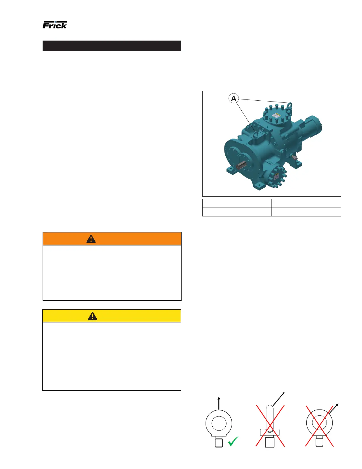
You can move the compressor with rigging, using a crane
or forklift, by hooking into the two lifting rings at each end
of the main housings. Only use the compressor lifting rings
to lift the compressor itself.
Figure 6: Lifting rings
Callout Component
A Lifting rings
Lifting instructions
Lifting rings are located to facilitate the rigging and lifting
of the bare compressor. See Figure 6. Ensure that only a
qualied operator performs the lifting and that they follow
the necessary precautions.
• Lift rings are intended for lifting the bare compressor
only.
• Examine the lift rings for damage before lifting the
compressor. Replace any damaged rings.
• Fully screw in the lift rings and seat them rmly against
the contact surface before lifting.
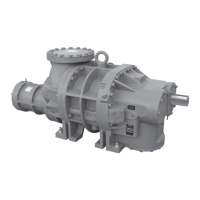
• Load the lift rings in the vertical direction only.
Ensure that the load is parallel to the threaded portion
of the lift ring. See Figure 7. This may require the use
of a spreader beam. Loading the lift rings at an angle
reduces their load capacity.
• Ensure that the load is level and stable before lifting
more than a few inches.
• Lift the compressor slowly.
• Remove the lift rings from the compressor before
operation. The vibration of a running compressor can
cause the lift rings to loosen and become damaged.
Figure 7: Lifting rings orientation
HPS 273 and 407 compressors are designed to be driven
with an open drive, foot-mounted motor. Do not exceed
the rotor and bearing design set limitations: refer to Cool-
Ware for more information. Refer to 090.040-O, Quantum
HD Control Panel for additional information on setpoint
limits.
Outline dimensions
Find complete dimensions and connection information on
the outline drawing, which you can request by contacting
Johnson Controls-Frick Sales. See Figure 11 and Figure 12.
Holding charge and storage
Every HPS 273 and 407 compressor is pressure and leak
tested at the Johnson Controls–Frick factory and thor-
oughly evacuated and charged with dry nitrogen to ensure
its integrity during shipping and short-term storage before
installation.
Keep all compressors in a clean, dry location to prevent
corrosion damage. For compressors stored for more than
two months, check their nitrogen charge periodically.
See General information for complete instructions and
refer to 020.050-W Limited Warranty Screw Compressor
Purchased for Long-Term Storage for FRICK Bare Screw
compressors.
Warning
Holding-charge shipping gauges, if mounted, are
rated for 2.1 bar (30 psig) and are for checking the
shipping charge only. They must be removed before
pressure testing and operating the system. Failure to
remove these gauges may result in catastrophic fail-
ure of the gauge resulting in serious injury or death.
Access valves are bronze and they must be replaced
with steel plugs when package is assembled.
Caution
This equipment has been pressurized with nitrogen
gas. Temporary valves and gauges have been in-
stalled.
1. Relieve pressure before opening lines or making
eld connections.
2. Remove charging valves or gauges be pressurizing
system.
3. Refer to installation operation and maintenance
manual for additional information.
Escaping gas may cause injury.