070.750-IOM2 (JUN 22)
Page 7
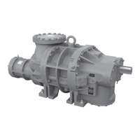
HPS 273 and 407 Rotary Screw Compressor
Installation - Operation - Maintenance
Volumizer variable volume ratio control
Screw compressors do not have regulating valves in the
suction and discharge ports of the compressor body to
regulate the opening and closing of ports. Instead, the
geometry of the rotors and housings define the port open-
ings and closings and subsequently the swept volume of the
compressor.
On the inlet end of the compressor, refrigerant vapor fills
the volume of the rotor threads until the rotor rotates to a
position that closes off the suction port. On the discharge
end of the compressor the same rotor thread opens to the
discharge port in the housing, ideally when the pressure
inside the thread is equal to the outside system pressure.
If the internal thread pressure is higher, over-compression
occurs, and if the internal thread pressure is lower, then
under-compression occurs; in both situations the unit is
inefcient. The pressure inside the threads is affected by
temperature, volume, the presence of a non-compressible
liquid, such as the oil, and leakage due to internal clear-
ances. The ratio of the rotor thread volume at the suction
end divided by the rotor thread volume at the discharge
end is dened as the compressor volume ratio (Vi). Because
the mass ow at the suction port and the mass flow at the
discharge port are the same, you can calculate the vol-
umes at these locations using their respective values of gas
densities.
The Frick compressor includes a method of varying the
internal Vi to match the system pressure ratio. Control of
the internal Vi eliminates the power penalty associated with
over- or under-compression. Vi control is achieved by the
use of a slide stop, a movable portion of the rotor hous-
ing assembly that moves axially with the rotors to control
discharge port location.
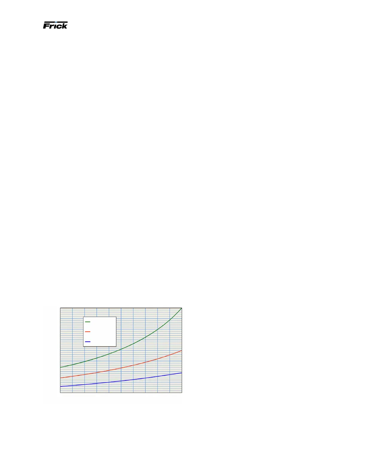
HPS compressors are available in three different Vi ranges;
2.2 to 5.0, 1.7 to 3.0, and 1.3 to 1.96, and the relationship
between the Vi and slide stop position is shown in the fol-
lowing figure:
Figure 4: HPS compressors volume ratio, Vi
Stepless capacity control
Capacity control is achieved by use of a movable slide valve.
The slide valve moves axially under the rotors to provide
fully modulated capacity control from 100% to approxi-
mately 20% minimum load capacity. Approximate minimum
load capacity varies slightly with compressor model, pres-
sure ratio, discharge pressure level, and rotor speed.
The slide valve is positioned by hydraulic movement of its
control piston. When in the unloaded position, gas is by-
passed back to suction through a recirculation slot before
compression begins and any work is expended, providing
the most efcient unloading method available for part-
load operation of a screw compressor.
Oil pump, optional
A demand oil pump is required for low differential pressure
applications.
Note: CoolWare provides a warning when the oil differen-
tial pressure is too low.
Oil being supplied to the compressor from the oil separa-
tor is at the system discharge pressure minus the pressure
drop in the oil system piping, oil lter, and valves. Oil port-
ing to all parts of the compressor is vented back to a loca-
tion in the compressor’s body that is at a lower pressure
than compressor discharge pressure. All oil entering the
compressor is moved by the compressor rotors, out the
compressor outlet, and back to the system oil separator.
Balance piston oil requirements and regulation
When operating, the discharge pressure of a compressor
can force the rotors back towards the suction, creating a
load on the thrust bearing assembly. In cases where the
discharge pressure is high, this axial load can be exces-
sive for the compressor’s thrust bearings and limit their
operating life. To compensate for this situation, a balance
piston assembly is designed to generate a counter force
that reduces the load on the thrust bearings and increases
their operating life.
In a conventional balance piston arrangement, oil pressure
enters the compressor, which is regulated by an outlet
pressure regulating valve and orice. This regulated oil
pressure acts against an internal piston that generates a
force to counter the rotor thrust. The problem is that the
conventional balance piston regulator is set for a specic
operating condition and when the load or operating condi-
tions vary the balance piston pressure may be insufcient.
HPS models use a motorized balance piston regula-
tor controlled by a programmable logic controller (PLC).
The PLC compensates for the changing compressor load
and conditions by continually calculating the oil pres-
sure required to maintain the necessary counter force.
The PLC accomplishes this by monitoring seven different
inputs: compressor Vi, suction pressure, slide valve posi-
tion, economizer pressure, discharge pressure, operating
speed, and oil pressure. It uses these values to identify the
target pressure for the balance piston regulator in a look
up table. The PLC communicates this new target pressure
to the balance piston regulator controller and the valve is
modulated to generate the target oil pressure.
HPS models have balance pistons on the male and female
inlet end of the compressor rotors with oil supplied
through the SB-2 port.
1.00
0% 10% 20% 30% 40% 50% 60% 70% 80% 90% 100%
2.00
3.00
4.00
1.50
2.50
3.50
4.50
5.00
Volume ratio
Vi = 2.2 - 5.0
Vi = 1.7 - 3.0
Vi = 1.3 - 1.96
Slide stop travel (SS), 0% to 100%