S90-010 M FRICK
QUANTUM™ COMPRESSOR CONTROL PANEL
Page 8 MAINTENANCE
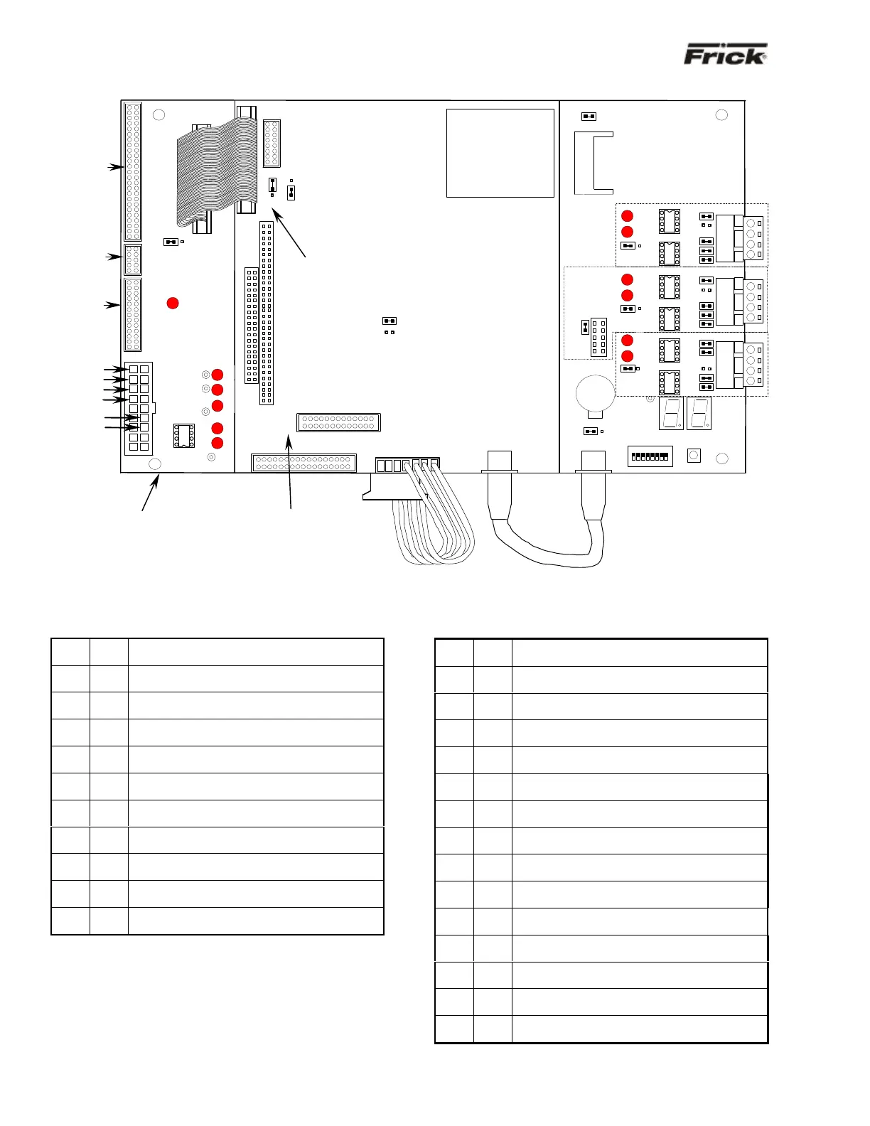
QUANTUM™ 3 CONTROLLER BOARD PICTORIAL
Note: There are duplicate numbers for the links on the processor (smaller) board and the communications (larger) board. If you must make a
change to a jumper (link), then ensure that you modify the correct link.
QUANTUM™ 3 BOARD SETTINGS
Processor Board Jumpers
LK2
A
B *
COM3 IRQ4
COM3 IRQ11
LK3
A
B *
COM4 IRQ3
COM4 IRQ10
LK4
in
out*
RS-422 Terminated
RS-422 Not Terminated
LK5
in*
out
RS-485 Receiver Enabled
RS-485 Receiver Disabled
LK6
in*
out
RS-485 Terminated
RS-485 Not Terminated
LK7
in*
out
Watchdog timer Enabled
Watchdog timer Disabled
LK8
in
out*
2 second Watchdog timer timeout
8 second Watchdog timer timeout
LK10
A
B *
+5V Backlight Voltage (Samsung, NEC, Sharp)
+12V Backlight Voltage (LG Philips Display)
LK11
A
B *
+5V LCD Supply (Samsung, NEC, Sharp)
+3.3V LCD Supply (LG Philips Display)
LK12
in*
out
Bit 1 of 259H “Logic 1” User Application Link
Bit 1 of 259H “Logic 0” User Application Link
LK13
in*
out
Bit 2 of 259H “Logic 1” User Application Link
Bit 2 of 259H “Logic 0” User Application Link
* Standard Setting
Communications Board Jumpers
LK1
in
out*
Pull down COM1
No pull down
RS-422/485 (Rx-/Tx-)
LK2
in
out*
Terminate COM1
No termination
RS-422/485
LK3
in
out*
Pull up COM1
No pull up
RS-422/485 (Rx+/Tx+)
LK4
in
out*
Pull down COM1
No pull down
RS-422 (Tx-)
LK5
in
out*
Pull up COM1
No pull up
RS-422 (Tx+)
LK6
in
out*
Pull down COM2
No pull down
RS-422/485 (Rx-/Tx-)
LK7
in
out*
Terminate COM2
No termination
RS-422/485
LK8
in
out*
Pull up COM2
No pull up
RS-422/485 (Rx+/Tx+)
LK9
in
out*
Pull down COM2
No pull down
RS-422 (Tx-)
LK10
in
out*
Pull up COM2
No pull up
RS-422 (Tx+)
LK16
A *
B
COM1 RS-485
COM1 RS-422
LK17
A *
B
COM2 RS-485
COM2 RS-422
LK19
in*
out
Select RS-422/RS-485 for COM2
Select RS-232 for COM2
LK20
A *
B
Battery Backup Enabled
Battery Backup Disabled (CMOS Cleared)
LK25
in*
out
Select Compact Flash card as master device
Select Compact Flash card as slave device
* Standard Setting
Power-I/O
Com. Cable
This assembly is shipped with
LK11 set to position “B”. If a
Samsung, NEC, or Sharp
display is being used, then
LK11 must be changed to
position “A”.
Keypad
Cable
LCD
Display
Cable
LCD
Backlight
Cable
HEAT SINK
COM2
MEMORY
Pack
RS-
422
RS-
485
RS-
422
RS-
RS-
422
RS-
(large bottom board)
(small top board)