RWB II ROTARY SCREW COMPRESSOR UNITS
INSTALLATION
S70-200 IOM
Page 11
B
C
A
OPT. OIL TEMP
CONTROL VALVE
HOT
REFRIGERANT
OUT
REFRIGERANT IN
COOL
COOL
OIL OUT
HOT OIL IN
LIQUID
LEVEL
STATIC HEAD
TO OVERCOME
CONDENSER
PRESSURE DROP
6 Ft.
Min.
SYSTEM
CONDENSER
SAFETY
VALVE
VAPOR
THERMOSYPHON
RECEIVER
LIQUID OVERFLOW
DRAIN TO RECEIVER
TO SYSTEM
EVAPORATOR
SYSTEM
RECEIVER
1
3
4
(Mounted below Thermosyphon
receiver level)
2
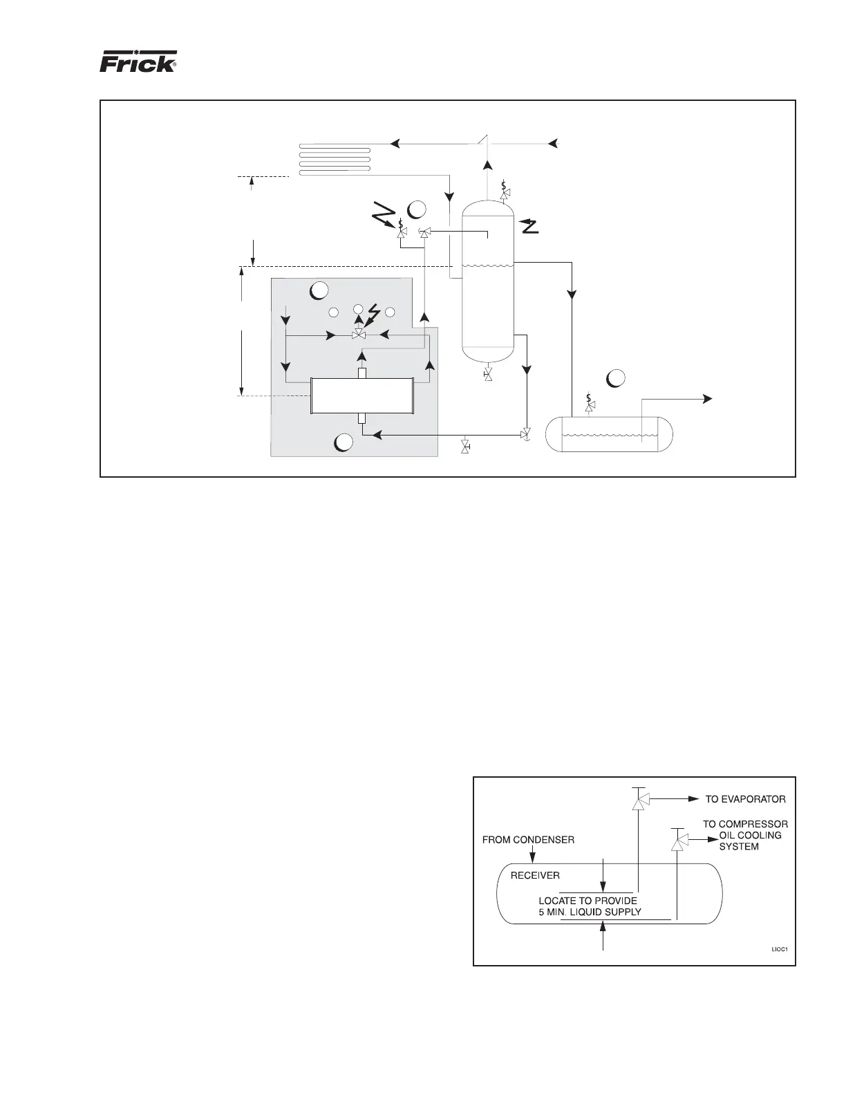
PLATE COOLER
TSOC
LIQUID INJECTION OIL COOLING
(OPTIONAL)
The liquid injection system provided on the unit is self-con-
tained but requires the connection of the liquid line sized as
shown in the table and careful insertion of the expansion
valve bulb into the thermowell provided in the separator.
High pres sure gas is connected through the regulator to
the ex ter nal port on the liquid injection valve to control oil
tem per a ture.
NOTE: For booster applications the high pressure gas
con nec tion must be taken from a high side source (high
stage compressor discharge). This should be a 3/8" line
con nect ed into the solenoid valve provided. This gas is
required by the expansion valve external port to control
oil temperature.
It is IMPERATIVE that an uninterrupted supply of high pres-
sure liquid refrigerant be provided to the in jec tion system at
all times. Two items of EXTREME IMPOR TANCE are the
design of the receiver/liquid in jec tion supply and the size of
the liquid line.
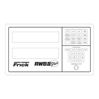
It is recommended that the receiver be oversized suffi cient ly
to retain a 5-minute supply of refrig erant for oil cool ing. The
evaporator supply must be secondary to this con sid er ation.
Two methods of accomplishing this are shown.
The dual dip tube method uses two dip tubes in the re ceiv er.
The liquid injection tube is below the evapor ator tube to
en sure continued oil cooling when the receiver lev el is low.
See Figure 9.
Figure 8
1.
The thermosyphon oil cooler is supplied with the oil side piped to the compressor unit and stub ends supplied on the re frig -
er ant side.
2. A three-way oil temperature control valve is required where condensing temperature is expected to go below 65°F.
3. A refrigerant-side safety valve is required in this location only when refrigerant isolation valves are installed between the cooler
and thermosyphon receiver. If no valves are used between the cooler and TSOC receiver, the safety valve on the TSOC receiver
must be sized to handle the volume of both vessels. Then, the safety valve on the cooler vent (liquid refrigerant side) can be
eliminated.
4. The system receiver must be below the thermosyphon receiver in this arrangement.
Figure 9