RWB II ROTARY SCREW COMPRESSOR UNITS
INSTALLATION
S70-200 IOM
Page 16
CONTROL POWER REGULATOR
Compressor units that will be used in areas that suffer brown-
outs and other signifi cant power fl uctuations can be sup plied
with a control power regulator. See the following il lus tra tion,
Rec om mend ed Regulator Installation.
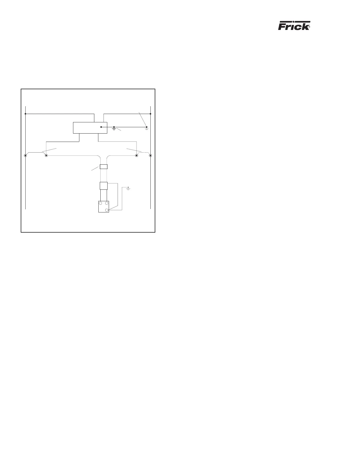
RECOMMENDED REGULATOR INSTALLATION
REMOVE JUMPERS 6 TO 6B & 2 TO 2B
DC POWER
EMI FILTER
SUPPLY
SEE SOLA CONNECTION CHARTS FOR
INPUT & OUTPUT CONNECTIONS
6
REMOVE FERRITE TUBE
WHEN SOLA IS ADDED,
6B
6
H
NOTE: AT SOLA ASSEMBLY, MAKEWIRES 6, 2, GND, 6B, & 2B,
10 FT LONG. CUTWIRESTO LENGTH AT INSTALLATION
H5
REGULATOR
H3H4
OUTPUT
INPUT
X1
120/240 V. IN, 120 V. OUT
SOLA #63-23-112-4, 120 VA, 60 HZ
SHOWN HERE- CONSULT FRICK
FOR OTHER VOLTAGES/HZ
SOLA ENCLOSURE
GND TERM
2A6A
23
PS 1
1
LINE
LOAD
GREEN
FERRITE
TUBE
2B
2
GND LUG IN
H2 H1
LUG
X2
GREEN
GND TERM
IN MICRO
2
N
Figure 16
BATTERY BACKUP
The battery backup is used only for date and time retention
during pow er in ter rup tion. All setpoints and other critical
in for ma tion are saved to onboard fl ash memory.
NOTE: It is not necessary to disconnect the battery
back up during extended downtime.