RWB II ROTARY SCREW COMPRESSOR UNITS
OPERATION
S70-200 IOM
Page 17
OPERATION and START-UP INSTRUCTIONS
The Frick RWB II Rotary Screw Compressor Unit is an in te -
grat ed system con sist ing of six major subsystems:
1. Control Panel (See publication S90-010 O, M, & CS for
Quantum Panel and S70-200 OM for the Plus panel).
2. Compressor
3. Compressor Lubrication System
4. Compressor Oil Separation System
5. Compressor Hydraulic System
6. Compressor Oil Cooling System
7. Compressor Easy-Start System
The information in this section of the manual provides the
logical step-by-step in struc tions to properly start up and
op er ate the RWB II Rotary Screw Com pres sor Unit.
The following subsections must be read and un der stood
be fore at tempt ing to start or operate the unit.
TDSH COMPRESSOR
The Frick RWB II rotary screw compressor utilizes mating
asymmetrical profi le helical rotors to provide a con tin u ous
fl ow of refriger ant vapor and is designed for both high pres-
sure and low pressure applica tions. The com pres sor incorpor-
ates the following features:
1. High capacity roller bearings to carry radial loads at both
the inlet and outlet ends of the compres sor.
2. Heavy-duty, four-point angular contact ball bearings
to carry axial loads are mounted at the discharge end of
com pres sor.
3. Balance pistons located in the inlet end of the compres sor
to reduce axial loads on the axial load bearings and in crease
bearing life.
4. Moveable slide valve to provide infi nite step capacity
con trol from 100 to 10%.
5. VOLUMIZER® volume ratio control to allow infi nite ly vari-
able volume ratio from 2.2 to 5.0 during compres sor op er a tion
for all models except 480 which is 2.2 to 4.2.
6. A hydraulic unloader cylinder to operate the slide stop
and slide valve.
7. Bearing and casing design for 350 PSI discharge pres sure.
This PSI rat ing applies only to the com pres sor and does
not re fl ect the design pres sure of the var i ous sys tem
com po nents.
8. All bearing and control oil vented to closed thread in the
compressor instead of suction port to avoid performance
penalties from superheating suction gas.
9. Shaft seal design to maintain operating pressure on seal
well below discharge pressure, for increased seal life.
10. Oil injected into the rotors to maintain good volumetric and
adiabatic effi ciency even at very high compression ra tios.
11. Shaft rotation clockwise facing compressor, suitable for
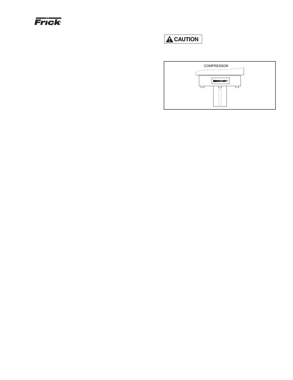
all types of drives. SEE CAUTION.
12. Dual compressor casing design for very low airborne
noise trans mis sion.
COMPRESSOR RO TA TION IS
CLOCK WISE WHEN FAC ING THE
COMPRESSOR DRIVE SHAFT. THE
COM PRES SOR SHOULD NEVER BE OP ER AT ED IN RE-
VERSE RO TA TION AS BEAR ING DAM AGE WILL RE SULT.
Figure 17
COMPRESSOR LUBRICATION SYSTEM
The lubrication system on an RWB II screw com pres sor unit
performs several functions:
1. Provides lubrication to bearings and seal.
2. Provides a cushion between the rotors to minimize noise
and vibrations.
3. Helps keep the compressor cool and prevents
overheat ing.
4. Provides an oil supply to hydraulically actuate the slide
valve and slide stop.
5. Provides oil pres sure to the balance pistons to help in-
crease bearing life.
6. Provides an oil seal between the rotors to prevent rotor
contact or gas bypassing.
The compressor unit may be equipped with either a no
pump or a demand pump lu bri ca tion system. Ad di tion al ly,
either sys tem may con tain dual oil fi lters and liquid in jec tion,
wa ter-cooled, or thermosyphon oil cooler for com pres sor
oil cool ing.
NO PUMP OIL SYSTEM
The RWB II screw compressor unit is designed to be self-lu-
bricating. Oil being supplied to the compres sor from the oil
separator is at system head pressure. Within the com pres sor,
oil porting to all parts of the compressor is vent ed back to a
point in the compres sor’s body that is at a pres sure lower than
compressor discharge pressure. The com pres sor’s normal
operation makes the com pres sor unit operate es sen tial ly as
its own oil pump. All oil entering the compressor is moved by
the compressor rotors out the com pres sor outlet and back
to the oil separator.
For normal high-stage operation an oil pump is not re-
quired.
COLD-START SYSTEM
The RWB II package is equipped with a special "cold start"
dis charge check valve on the gas outlet connection of the
oil sep a ra tor (see Figure 18). This valve causes the oil sep a -
ra tor to de vel op oil pressure rapidly on initial start in order to
lu bri cate the com pres sor without requiring an oil pump, even
in cold am bi ent tem per a tures with all pressures equal ized.