RWB II ROTARY SCREW COMPRESSOR UNITS
MAINTENANCE
S70-200 IOM
Page 36
Completely load the slide valve. The display at this time
should indicate 100%. If the display is less than 100%, ad just
po ten ti om e ter POT #3 on the SBC until 100% is in di cat ed.
Repeat this sequence until the slide valve indicates 0% fully
unloaded and 100% fully loaded.
VOLUMIZER
®
POTENTIOMETER
REPLACEMENT AND ADJUSTMENT
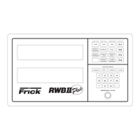
The VOLUMIZER
®
potentiometer is located under a cover
on the right side of the compressor (facing shaft) at the inlet
end. See Figure 33.
1. Shut off control power.
2. Remove the potentiometer cover and gasket.
3. Remove the potentiometer and mounting brack et.
4. Install new potentiometer and bracket.
Figure 33
5. ADJUSTMENT must be made with the com pres sor run-
ning and the slide valve fully unloaded. With the slide stop
at maximum (Vi) position, check that the po ten ti om e ter
pushrod is in contact with the slide stop pushrod. If not, the
bracket must be ground or trimmed until contact is made.
Complete ly decrease the slide stop. The Operating display
at this time should indicate a (Vi) of 2.2. If greater than 2.2,
adjust potentio meter POT #2 on the SBC until 2.2 is in di -
cat ed. If 2.2 is not ob tainable, get as close as possible and
proceed to the next step. Adjustment of POT #2 and POT #1
are interac tive and POT #1 may require adjustment to allow
POT #2 to come into range. Now, completely in crease the
slide stop. The display at this time should in di cate a (Vi) of
5.0 (4.2 for model 480). If less than 5.0 (4.2 for model 480),
adjust poten tiometer POT #1 on the SBC until 5.0 (4.2 for
model 480) is in di cat ed. Repeat this se quence until the slide
stop indicates 2.2 when fully de creased and 5.0 (4.2 for model
480) when fully increased.
NOTE: The total travel on the VOLUMIZER
®
po ten ti om e ter
is .394 inch.
SV POSITION POTENTIOMETER
REPLACEMENT AND ADJUST MENT
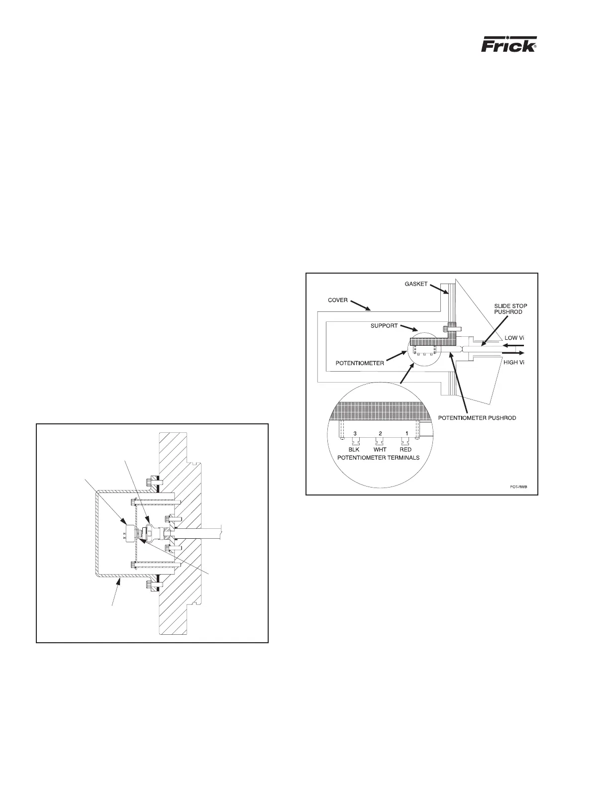
The Slide Valve Position potentiometer is located on the end
of the compressor unloader cylinder (see Figure 32).
1. Shut off control power.
2. Remove the four socket head cap screws securing the
potentiometer cover to the unloader cylinder.
3. Unsolder leads to the potentiometer and remove.
4. Loosen the setscrew on the potentiometer side of the
fl e x i ble coupling.
5. Remove the three retainer clips securing the poten tiometer
to the base plate. The potentiometer should slip out of the
coupling.
6. Install the new potentiometer and reassemble.
7. Adjustment:
ROUGH ADJUSTMENT is made with the slide valve fully
unloaded and the control power off. Remove connector P5.
With a digital volt me ter, measure the resistance across the
red and white wires, having removed them from the SBC.
The resistance should be 1000 +/- 50 ohms. If adjustment is
necessary, loosen the locknut and rotate the po ten ti om e ter
clock wise or counterclock wise until the re sis tance read ing
is a close to a 1000 ohms as possible. Retighten the lock nut
and replace wires. NOTE: Me chan i cal travel of the slide
valve potentio meter is 300 de grees rotation when the
slide stop is confi rmed to be in the 2.2 Vi po si tion. The
travel will be less than 300 degrees if the slide stop is
in any position above 2.2 Vi.
POTENTIOMETER
FLEXIBLE
COUPLING
COVER
LOCKNUT
Figure 32
FINE ADJUSTMENT must be made with the slide valve ful ly
unloaded and the compressor running. The Op er at ing dis play
at this time should indicate a slide valve position of 0%. If
the display is greater than 0%, adjust potentio meter POT
#4 on the SBC until 0% is indicated. If 0% is not at tain able,
get as close as possible and then proceed to the next step.
The adjust ments of POT #4 and POT #3 are interactive and
POT #3 may require adjustment to allow POT #4 to come
into range.