RWB II ROTARY SCREW COMPRESSOR UNITS
MAINTENANCE
S70-200 IOM
Page 23
pres sure and spring ten sion are suf fi cient to main tain clo sure
on unit shut down. A me ter ing valve is also pro vid ed for use as
a service valve and to allow dis charge gas fl ow reg u la tion to
prevent ex ces sive force and resulting clo sure “ham mer ing”.
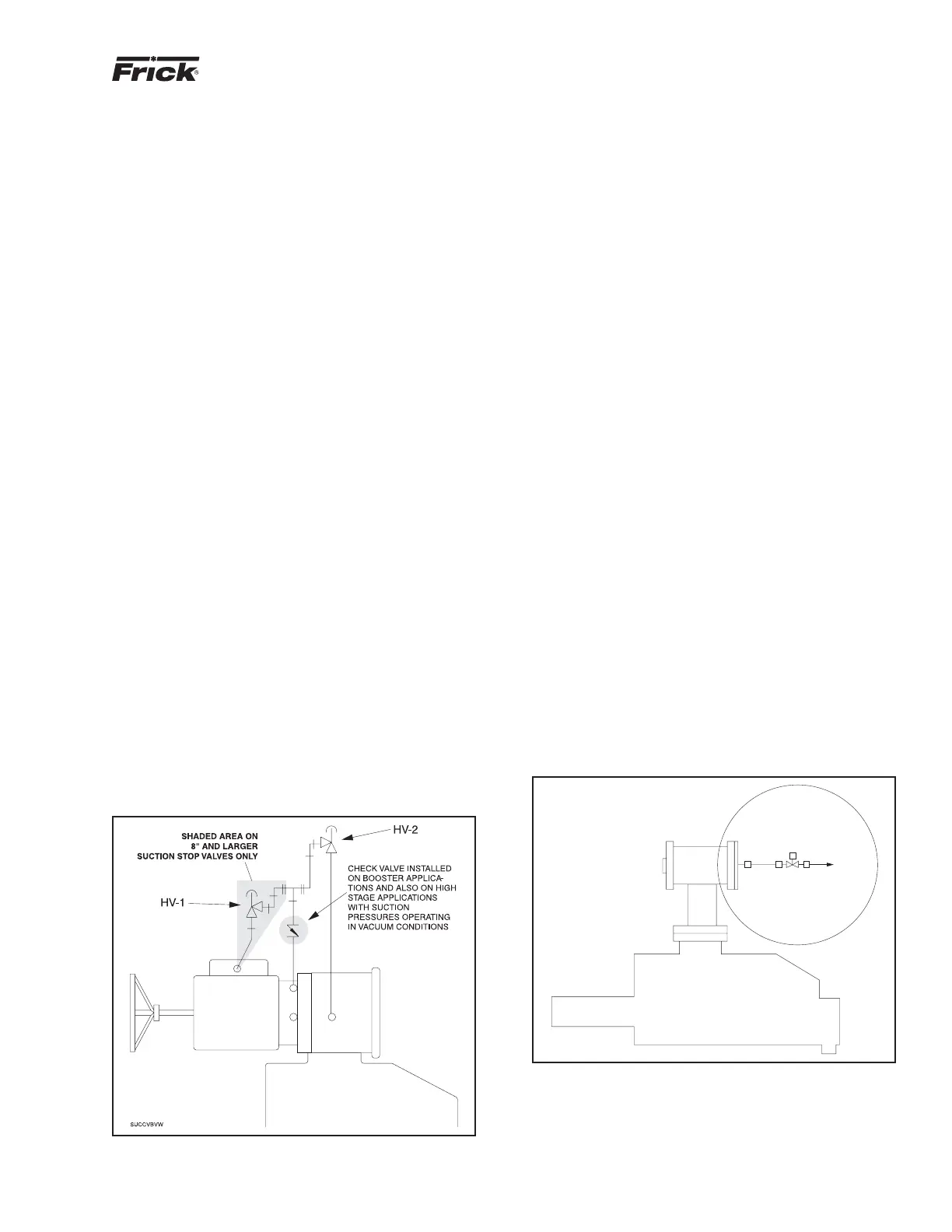
SUCTION CHECK VALVE BYPASS
During normal operation, valve HV1 is closed. This is a pump-
out connection to allow refrigerant removal to the system
suction prior to evacuation for servicing. Valve HV-2 must
be open in most systems at all times. It should normally be
cracked open to allow the oil separator to slowly bleed down
to system suction pressure when the unit is stopped (hav ing
this valve cracked open allows the compressor drive mo tor to
have an easier start, and the discharge check valve will seat
more tightly). If the drive coupling backspins, start closing the
valve until the backspin stops. If the sep a ra tor oil lev el foams
ex ces sive ly on shutdown, HV-2 should be closed slight ly. If
the separator takes more than 20 – 30 minutes to equalize
to suction pressure after shut down, HV-2 can be opened
slightly. See Figure 24.
NOTE: HV-2 should be closed on systems with suc tion
pres sures below atmospheric pressure, to avoid the pos-
si bil i ty of air leakage into the system during shut down.
However, on high-stage or boost er sys tems with check
valve, HV-2 can remain open.
HV-2 also should be closed on systems that utilize au to cy cle
to restart the compressor, based on increase in sys tem
suc tion pressure during shutdown, if slowly bleed ing the
oil sep a ra tor gas to suction will raise the suction pres sure
enough to cause short cycling of the compressor.
Also it is important to close HV-2, if the oil pump is to be run
for long periods of time with the compressor stopped, to avoid
oil being pumped up the suction line.
If multiple compressors are operated with a common econ-
o miz er vessel, it is necessary to install a back-pressure
reg u la tor valve with an electric shut-off option in the vapor
line piped to the compressor's economizer port. If an electric
shut-off is not installed in the economizer vapor line, valve
HV-2 must remain closed to avoid a gas bypass from the
econ o miz er line through the suction check valve bypass, back
to the suction line on a compressor that is shut down.
Figure 24
LOW AMBIENT OPERATION
It is recommended that oil separators be insulated as a min-
i mum requirement to preserve the heat generated by the oil
heaters. It is important that the coalescer end of the sep a ra tor
be insulated to prevent refrigerant con den sa tion.
On systems located outdoors or in unheated buildings where
the ambient temperature could drop below +40°F, in su lat ing
and/or heat tracing of the compressor lube oil systems is
highly recommended.
When low ambient temperatures (below +20°F) are a pos-
si bil i ty, it is recommended that lube oil lines, oil fi lters, oil
pumps and oil cool ers be heat traced and insulated.
Freeze-up protection must also be provided for all water-
cooled equipment
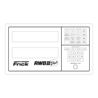
SUCTION CHECK VALVE
POWER ASSIST KIT
Low temperature booster compressor operations re quire a
more pos i tive suction check valve closure. This is ac com -
plished by al low ing the high pressure discharge gas to as sist
the spring tension and intermediate pres sure clos ing force.
The power assist kit (Figure 25) is factory in stalled with the
dis charge gas pressure being supplied from a con nec tion
on the dry end of the oil separator. It may be nec es sary to
pro vide high pressure gas from a high stage com pres sor
dis charge for booster applications in which the operating
pres sure differential on the booster compressor is in suf fi cient
to close the suction check valve.
Frick provides a power assist kit consisting of a mounted
and wired so le noid valve and tim er on all RDB booster
com pres sors. Introduction of high dis charge pres sure gas
is made to the check valve. A timer limits the high pressure
gas to only thirty sec onds du ra tion since in ter me di ate gas
pres sure and spring ten sion are suf fi cient to main tain clo sure
on unit shut down. A me ter ing valve is also pro vid ed for use as
a service valve and to allow dis charge gas fl ow reg u la tion to
prevent ex ces sive force and resulting clo sure “ham mer ing”.
POWER ASSIST KIT
TO COMPRESSOR
DISCHARGE
PWRASST
S
Figure 25