RWB II ROTARY SCREW COMPRESSOR UNITS
INSTALLATION
S70-200 IOM
Page 13
Due to the tendency of the port pressure to fall with de-
creasing compressor capacity, a back-pressure regulator
valve (BPR) is generally required on a fl ash economizer
sys tem (Figure 13) in order to maintain some preset pres-
sure dif ference be tween the subcooled liquid in the fl ash
vessel and the evaporato rs. If the back-pressure regulator
valve is not used on a fl ash econ o miz er, it is possible that
no pres sure dif fer ence will ex ist to drive liquid from the fl ash
vessel to the evaporators, since the fl ash ves sel pres sure
will ap proach suc tion pres sure at a de creased slide valve
po si tion. In cas es where wide swings in pres sure are an tic i-
pat ed in the fl ash econo mizer vessel, it may be nec es sary
to add an outlet pressure reg u la tor to the fl ash ves sel outlet
to avoid overpressurizing the econ o miz er port, which could
re sult in motor overload. Ex am ple: A sys tem feeding liquid
to the fl ash vessel in batches.
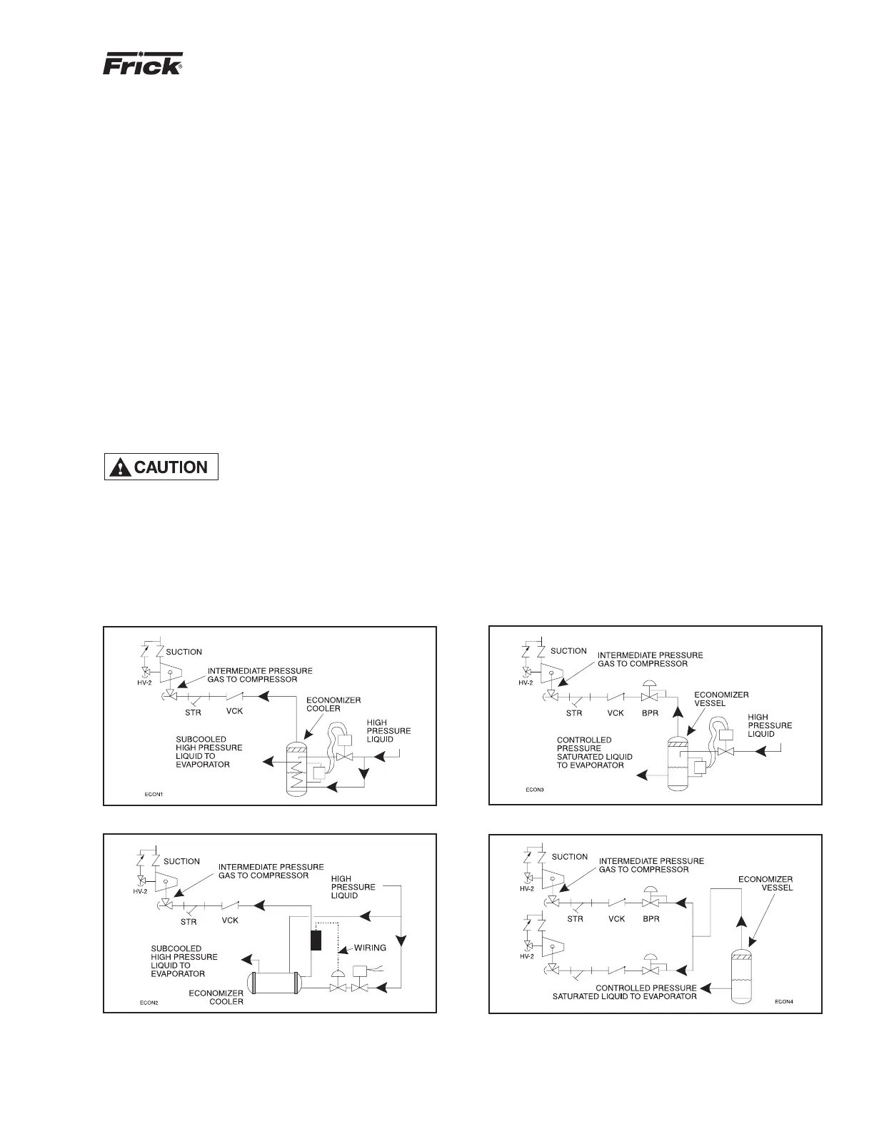
The recommended economizer systems are shown below.
Notice that in all sys tems there should be a strainer (STR)
and a check valve (VCK) between the economizer vessel
and the econ o miz er port on the compressor. The strainer
pre vents dirt from passing into the com pres sor and the check
valve prevents oil from fl owing from the com pres sor unit to
the econo mizer vessel during shut down.
Other than the isolation valve
need ed for strain er clean ing, it is
essential that the strain er be the
last device in the econ o miz er line before the compres-
sor. Also, pis ton-type check valves are recom mended
for in stal la tion in the econ o miz er line, as opposed to
disc-type check valves. The latter are more prone to gas-
pul sa tion-in duced failure. The isolation and check val ves
and strain er should be located as closely as pos si ble to
the com pres sor, pref er a bly within a few feet.
Figure 12 - Direct Expansion Economizer System
Figure 11 - Shell and Coil Economizer System
Figure 14 - Multiple Compressor Economizer System
Figure 13 - Flash Economizer System
For refrigeration plants employing multiple com pres sors on
a com mon econ o miz ing vessel, regardless of econ o miz er
type, each com pres sor must have a back-pressure regulat-
ing valve in order to bal ance the econ o miz er load, or gas
fl ow, between com pres sors. The prob lem of bal anc ing load
be comes most im por tant when one or more com pres sors
run at par tial load, ex pos ing the econ o miz er port to suction
pres sure. In the case of a fl ash ves sel, there is no need for
the re dun dan cy of a back-pres sure reg u lat ing valve on the
ves sel and each of the mul ti ple com pres sors. Omit the BPR
valve on the fl ash econ o miz er ves sel and use one on each
com pres sor, as shown in Figure 14. It is also rec om mend ed
that the back-pressure reg u lat ing valves, used on econ o miz er
lines, should be specifi ed with electric shutoff option. The
elec tric shutoff feature is nec es sary to pre vent fl ow from the
com mon econ o miz er vessel to the suction side of a stopped
com pres sor, through the suction check valve by pass line, if
the other com pres sors and the com mon econ o miz er vessel
are still op er at ing and the HV2 valve on the suc tion bypass
is open.
For refrigeration plants using a Packaged Refrigerant Re cir -
cu la tion (PRR) unit and a direct expansion (DX) econ o miz er
sys tem it is necessary to operate the liquid feed so le noid on
the PRR unit and the liquid feed solenoid on the DX vessel
off of a common signal to avoid liquid overfeed on the DX
economizer system.
If multiple compressors are operated with a common econ-
o miz er vessel, it is necessary to install a back-pressure
reg u la tor valve with an electric shutoff option in the vapor
line piped to the compressor's economizer port. If an electric
shut-off is not installed in the economizer vapor line, valve
HV-2 must remain closed to avoid a gas bypass from the
econ o miz er line through the suction check valve bypass, back
to the suction line on a compressor that is shut down.