070-450 IOM (NOV 13)
Page 14
XJF ROTARY SCREW COMPRESSOR
INSTALLATION
HOLDING CHARGE AND STORAGE
Every XJF compressor is pressure and leak tested at the
Johnson Controls–Frick factory and then thoroughly evacu-
ated and charged with dry nitrogen to ensure its integrity
during shipping and short term storage prior to installation.
All compressors must be kept in a clean, dry location to
prevent corrosion damage. Compressors that will be stored
for more than two months must have their nitrogen charge
checked periodically (see pages in GENERAL INFORMATION
for complete instructions).
WARNING
Holding-charge shipping gauges (if mounted) are rated
for 30 psig and are for checking the shipping charge
only. They must be removed before pressure testing
and operating the system. Failure to remove these
gauges may result in catastrophic failure of the gauge
resulting in serious injury or death.
Access valves are bronze and they must be replaced with
steel plugs when package is assembled.
WARNING
THIS EQUIPMENT HAS BEEN PRESSURIZED WITH
NITROGEN GAS. TEMPORARY VALVES AND GAUGES
HAVE BEEN INSTALLED.
1. RELIEVE PRESSURE PRIOR TO OPENING LINES OR
MAKING FIELD CONNECTIONS.
2. REMOVE CHARGING VALVES OR GAUGES PRIOR
TO PRESSURIZING SYSTEM.
3. REFER TO THIS MANUAL FOR ADDITIONAL
INFORMATION.
ESCAPING GAS MAY CAUSE INJURY !
SAE STRAIGHT THREAD O-RING FITTINGS - ASSEMBLY PROCEDURE FOR RXF 58 - 101
1. Inspect components to ensure that male and female
port threads and sealing surfaces are free of burrs, nicks
and scratches or any foreign material.
2. If the O-ring is not pre-installed to the tting on the
male end, install the proper size O-ring.
3. Lubricate the O-ring with a light coating of system oil or
petroleum jelly.
4. Screw the tting into the female port until the hex at
contacts the port face. Light wrenching may be necessary.
5. Tighten to the appropriate torque value shown in the
Assembly Torque Table.
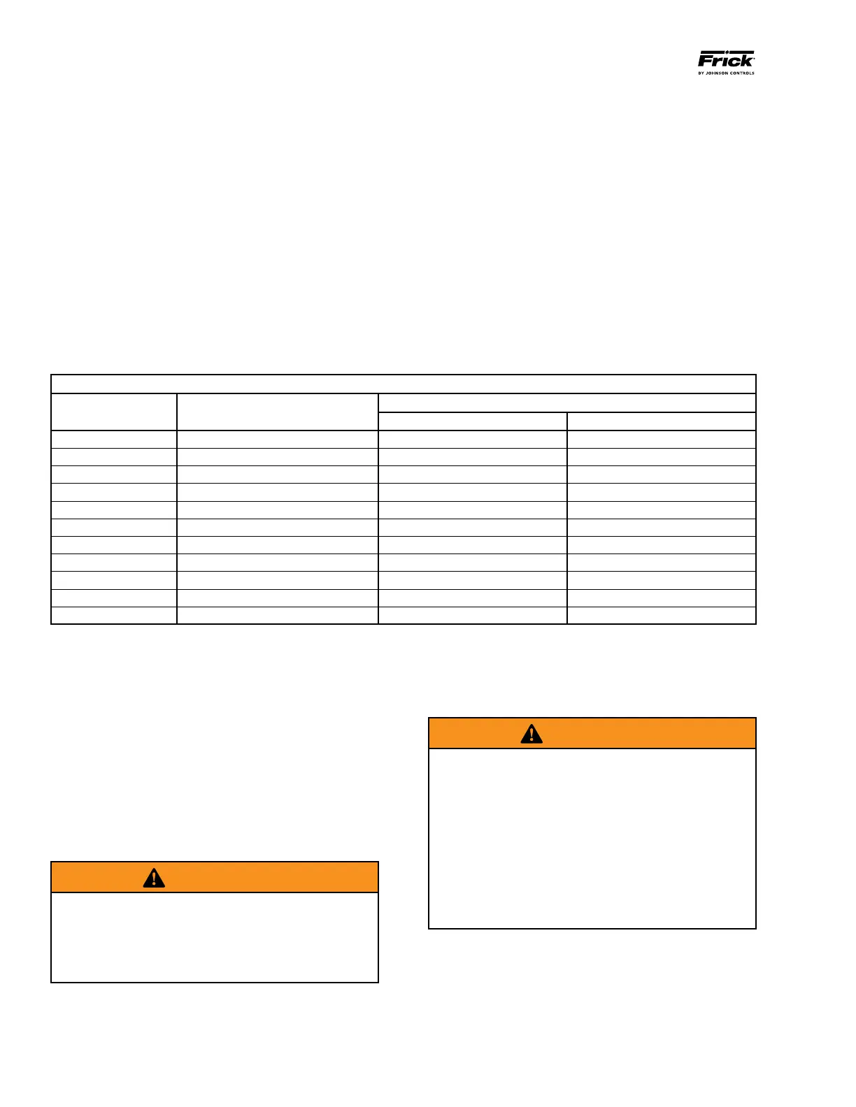
ASSEMBLY TORQUE TABLE
Straight and Adjustable Fittings or Plugs (steel)
Fitting Size SAE Port Thread Size
Assembly Torque
Inch lb Foot lb
2 5/16 – 24 65 ± 5 5.5 ± 0.5
3 3/8 – 24 130 ± 10 11 ± 1.0
4 7/16 – 20 170 ± 10 14 ± 1.0
5 1/2 - 20 260 ± 15 22 ± 1.0
6 9/16 – 18 320 ± 20 27 ± 2.0
8 3/4 - 16 500 ± 25 42 ± 2.0
10 7/8 – 14 720 ± 30 60 ± 2.5
12
1Z\zn – 12
960 ± 50 80 ± 5.0
16
1B\zn – 12
1380 ± 75 115 ± 6.0
20
1B\, – 12
2700 ± 150 225 ± 12.0
24
1M\, - 12
3000 ± 160 250 ± 12.0
When performing maintenance or replacing the compressor,
the hydraulic tubing may need to be removed and re-
installed. The following procedure outlines the proper
installation of SAE straight thread ttings to SAE straight
thread ports.
The male and female ends of SAE straight thread O-ring
ports have UN/UNF straight threads. An elastomeric O-ring
is tted to the male end. On assembly, the O-ring is rmly
sandwiched between the angular sealing surface of the
female port and the shoulder of the male end. Sealing is
thus affected and maintained by the O-ring compression
which results from the clamping force generated by the
tightening action. The straight threads do not offer sealing
action; they provide the resistance (holding power) for
service pressure.