070-450 IOM (NOV 13)
Page 15
XJF ROTARY SCREW COMPRESSOR
INSTALLATION
RIGGING AND HANDLING
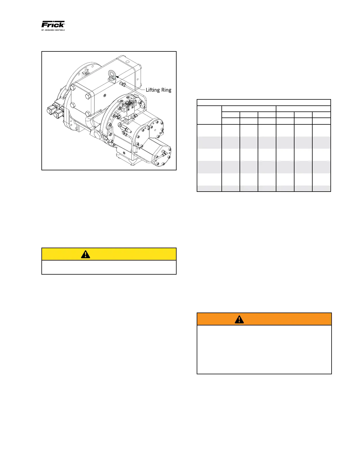
Figure 3 - Lifting Ring
The compressor can be moved with rigging, using a crane
or forklift, by hooking into the two lifting rings at each end
of the main housings. The compressor lifting rings shall only
be used to lift the compressor itself. See Figures 3 and 4.
FOUNDATION
Each XJF Rotary Screw Compressor is shipped mounted on
a wooden skid, which must be removed prior to unit
installation.
CAUTION
Allow proper spacing for servicing (see Dimensional
Outline Drawing).
The rst requirement of the compressor foundation is that
it must be able to support the weight.
XJF 95 600 lb
XJF 120 845 lb
XJF 151 1,210 lb
Screw compressors are capable of converting large
quantities of shaft power into gas compression in a relatively
small space. The compression process creates relatively
high frequency vibrations that require sufcient mass in the
base to effectively dampen them.
The best insurance for a trouble-free installation is to rmly
anchor the compressor to a suitable foundation using
proper bolting and by preventing piping stress from being
imposed on the compressor. Once the compressor is rigged
into place, its feet must be shimmed to level it. There must
be absolutely no stresses introduced into the compressor
body due to bolting of the feet and anges.
The compressor motor mount is not designed to carry the
unsupported weight of the motor. The full motor weight
must be supported using the motor lifting point during the
motor installation process. After the necessary bracket to
support the motor have been welded into place on the
package and the rear motor feet and the motor mount have
been bolted into place, the weight of the motor can rest on
the support bracket and the motor mount.
In any screw compressor installation, suction and discharge
lines should be supported in pipe hangers (preferably within
2 feet of vertical pipe run) so that the lines won’t move if
disconnected from the compressor. See table for Allowable
Flange Loads.
ALLOWABLE FLANGE LOADS
NOZ. MOMENTS (ft-lbf) LOAD (lbf)
SIZE AXIAL VERT. LAT. AXIAL VERT. LAT.
NPS M
R
M
C
M
L
P V
C
V
L
1 25 25 25 50 50 50
1.25 25 25 25 50 50 50
1.5 50 40 40 100 75 75
2 100 70 70 150 125 125
3 250 175 175 225 250 250
4 400 200 200 300 400 400
5 425 400 400 400 450 450
6 1,000 750 750 650 650 650
8 1,500 1,000 1,000 1,500 900 900
10 1,500 1,200 1,200 1,500 1,200 1,200
14 2,000 1,800 1,800 1,700 2,000 2,000
CUSTOMER CONNECTIONS
As a minimum you must make oil connections to the
locations shown on the compressor port location drawings
in addition to suction and discharge.
Other connections are available for instrumentation and
service as noted on the Dimensional Outline drawing. The
electrical connections for the slide stop and the slide valve
transmitters and the solenoid valve coils must be connected
to your control system .
The oil supply system for the compressor must be designed
for a total pressure drop of no more than 15 psi with a new
oil lter element. Excessive pressure drop in the oil circuit
can prevent proper operation of the slide valve and slide
stop pistons.
COMPRESSOR OIL
WARNING
DO NOT MIX OILS of different brands, manufacturers, or
types. Mixing of oils can cause excessive oil foaming,
nuisance oil level cutouts, oil pressure loss, gas or oil
leakage and catastrophic compressor failure. CoolWare
will select a specic Frick oil for the refrigerant being
used. Depending on the application, a different oil can be
selected provided it is of the proper viscosity and is com-
patible with the refrigerant and compressor elastomers.
OIL PUMP
If your XJF compressor application requires an oil pump, it
is recommended that a strainer be mounted upstream to
protect it. Frick supplied pumps are a positive displacement
gear type that must have a safety relief valve to ensure the
oil pressure will not be more than 50 psi above compressor
discharge pressure for all models.