070-450 IOM (NOV 13)
Page 20
XJF ROTARY SCREW COMPRESSOR
INSTALLATION
3. Set the compressor Vi to 3.5, then record the voltage that
is shown on the Slide Valve calibration screen for the cur-
rent Slide Valve and 0% Slide Valve positions. The difference
between these voltages must be in the 0.95 - 1.15 Vdc range.
4. Set the compressor Vi to 5.0, then record the voltage that
is shown on the Slide Valve calibration screen for the cur-
rent Slide Valve and 0% Slide Valve positions. The difference
between these voltages must be in the 0.73 - 0.93 Vdc range.
5. If the above voltage measurements are all in range, the
Volumizer II is working properly. If any of the voltages are
out of range, go to the troubleshooting section.
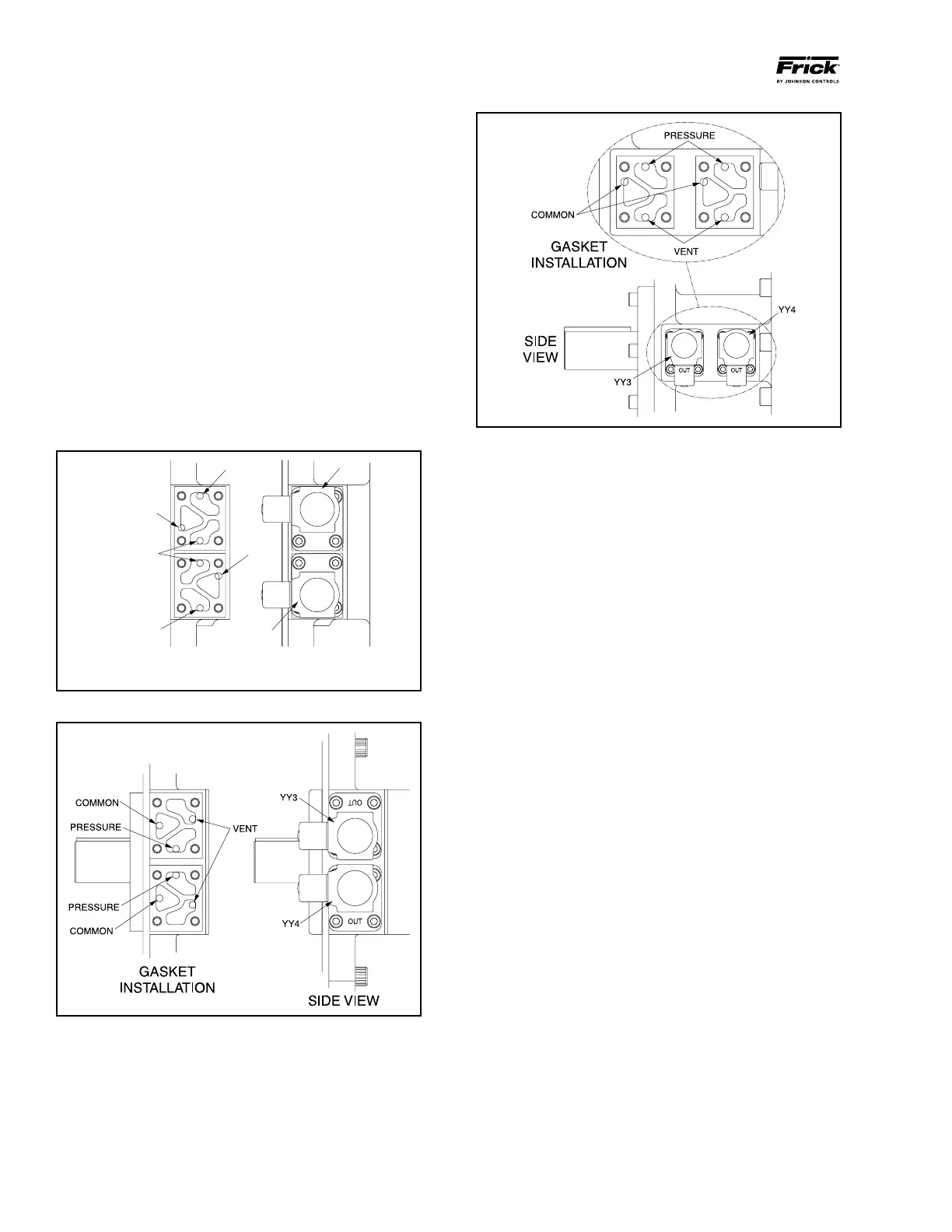
Proper installation of the Vi control valves and gaskets is
essential to the operation of this equipment. Incorrectly
installed parts may cause the compressor to operate at the
wrong Vi, or to load or unload improperly. Operation at the
wrong compressor Vi can cause excessive power consump-
tion, noise, vibration, or excessive oil foaming. See Figures
12 - 14 for correct installation of gaskets and location of
solenoids.
OUT
OUT
GASKET INSTALLATION SIDE VIEW
PRESSURE
PRESSURE
COMMON
COMMON
VENT
YY3
YY4
Figure 12 - XJF 95 Vi Control
Figure 13 - XJF 120 Vi Control
Figure 14 - XJF 151 Vi Control
LOW AMBIENT OPERATION
It is recommended that package oil separators be insulated
as a minimum requirement to preserve the heat generated
by the oil heaters, to prevent condensation and secure
lubrication at start-up.