070-450 IOM (NOV 13)
Page 18
XJF ROTARY SCREW COMPRESSOR
INSTALLATION
run at partial load, exposing the economizer port to suction
pressure. In the case of a ash vessel, there is no need for
the redundancy of a back-pressure regulating valve on the
vessel and each of the multiple compressors. Omit the BPR
valve on the ash economizer vessel and use one on each
compressor, as shown in Figure 7.
Figure 6 - Flash Economizer System
Figure 7 - Multiple Compressor Flash Economizer System
LIQUID INJECTION OIL COOLING
The liquid injection system provided on the unit is self-con-
tained but requires the connection of the liquid line sized as
shown in the table.
High-stage compressor units may be supplied with single-port
(low Vi, side, or closed thread) or dual-port (low Vi and high Vi),
liquid injection oil cooling. Single port will be furnished for low
compression ratio operation and dual port for high compres-
sion ratio operation. Booster compressor units use single-port
(High Vi), liquid injection oil cooling due to the typically lower
compression ratios.
The control system on high-stage units with dual-port, liquid
injection oil cooling switches the liquid refrigerant supply to
the high port when the compres sor is operating at higher
compression ratios (3.5 Vi and above) for best efciency.
Where low compres sion ratios (low condensing pressures)
are anticipated, thermo syphon or water-cooled oil cooling
should be used.
Liquid line sizes and the additional receiver volume (quanti-
ty of refrigerant required for 5 minutes of liquid injection oil
cooling) are given in the following table:
CONDITIONS: High Stage at 0°F Evap, and 95°F Cond, 10°F
suction superheat; Booster at -40°F Evap, 95°F Cond, 20°F
Intermediate, and 10°F suction superheat; R-507 unloaded
slide valve.
XJF
MODEL
LIQ. LINE SIZE*
5 MIN
SUPPLY
POUNDS
LIQUID
VOLUME
CU. FT
REFRIG
PIPE
SCH 80
TUBING
OD
R-717
HIGH
STAGE
95 3/8 – 12 0.3
120 1/2 – 33 0.9
151 3/4 – 65 1.8
R-507
HIGH
STAGE
95 3/8 1/2 24 0.4
120 3/8 1/2 60 1.0
151 1/2 5/8 99 1.6
R-717
BOOSTER
95 3/8 – 3 0.1
120 3/8 – 8 0.2
151 3/8 – 14 0.4
R-507
BOOSTER
95
No oil heat of rejection
at this condition
120
151
* 100 ft. liquid line. For longer runs, increase line size accordingly.
CAUTION
It is imperative that an uninterrupted high-pres sure
liquid refrig erant be provided to the injection system
at all times. Two items of EXTREME IMPORTANCE are
the design of the receiver/liquid injection supply and
the size of the liquid line. It is recommended that the
receiver be oversized sufciently to retain a 5-minute
supply of refrigerant for oil cooling. The evaporator
supply must be secondary to this considera tion. Failure
to follow these requirements causes wire draw which
can result in damage to the expansion valve, loss of oil
cooling, and intermittant oil cooling. One method of
ac complishing this is described below.
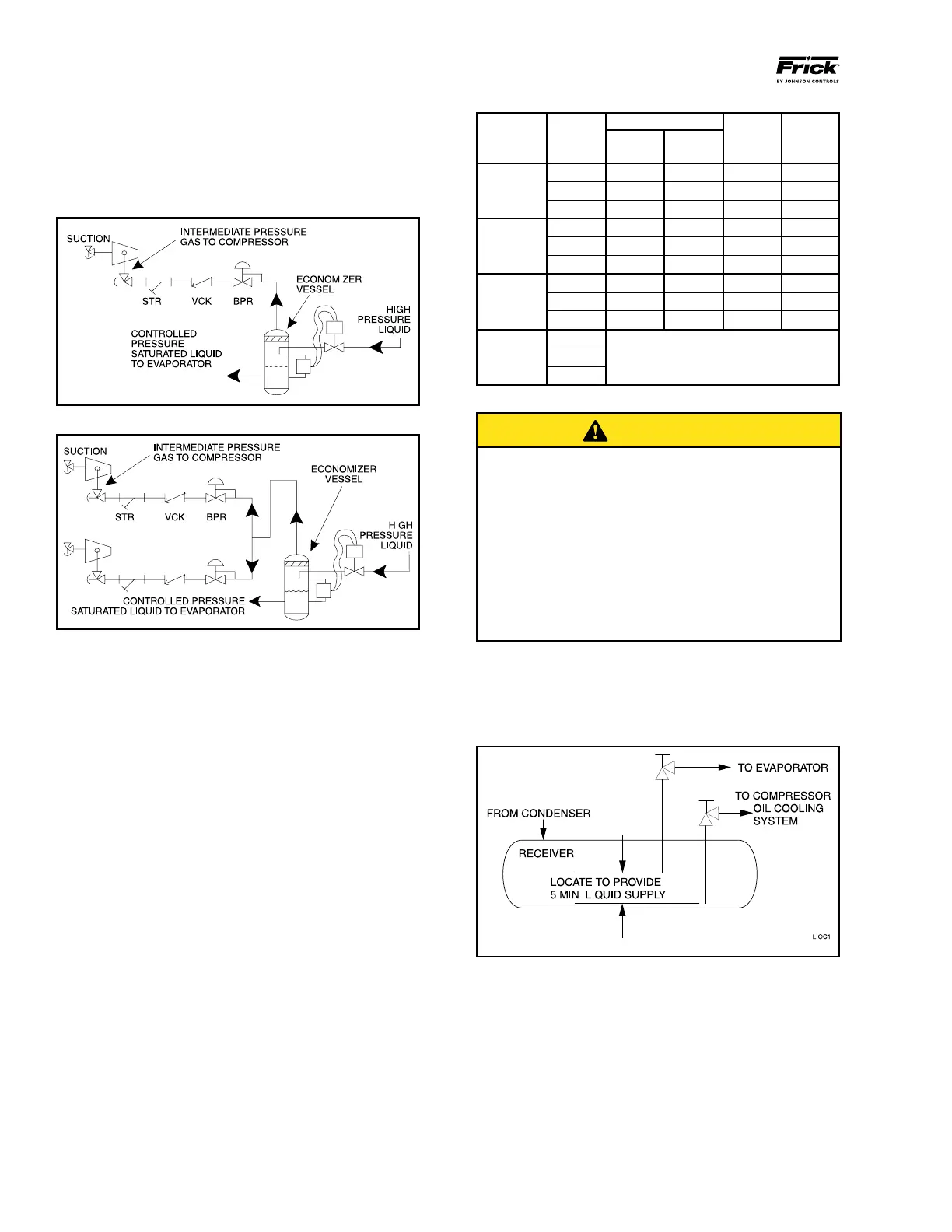
DUAL DIP TUBE METHOD
The dual dip tube method uses two dip tubes in the re ceiv-
er. The liquid injection tube is below the evaporator tube to
assure continued oil cooling when the receiver level is low.
See Figure 8.
Figure 8
DEHYDRATION / EVACUATION TEST
Evacuate the system to 1000 microns. Valve off the vacuum
pump and hold vacuum for one hour.
Pass – Vacuum cannot rise more than 500 microns during
one hour hold period.
Fail – Vacuum rise is more than 500 microns during one
hour hold period. Identify and repair any system leaks.
Repeat vacuum test until requirements are met.