070-450 IOM (NOV 13)
Page 3
XJF ROTARY SCREW COMPRESSOR
INSTALLATION - OPERATION - MAINTENANCE
THE INFORMATION CONTAINED IN THIS
DOCUMENT IS SUBJECT TO CHANGE
WITHOUT NOTICE
GENERAL INFORMATION
PREFACE
This manual has been prepared to acquaint the owner and
serviceman with the INSTALLATION, OPERATION, and
MAINTENANCE procedures as recommended by Johnson
Controls-Frick for XJF Rotary Screw Compressors.
It is most important that these compressors be properly ap-
plied to an adequately controlled refrigerant or gas system.
Your authorized Johnson Controls-Frick representative should
be consulted for his expert guidance in this determination.
Proper performance and continued satisfaction with these
units is dependent upon:
CORRECT INSTALLATION
PROPER OPERATION
REGULAR, SYSTEMATIC MAINTENANCE
To ensure correct installation and application, the equipment
must be properly selected and connected to a properly
designed and installed system. The Engineering plans,
piping layouts, etc. must be detailed in accordance with the
best practices and local codes, such as those outlined in
ASHRAE literature.
A screw compressor is a VAPOR PUMP. To be certain that it
is not being subjected to pumping liquid, it is necessary that
controls are carefully selected and in good operating
condition; the piping is properly sized and traps, if necessary,
are correctly arranged; the suction line has an accumulator
or slugging protection; that load surges are known and
provisions are made for control; operating cycles and stand
still periods are reasonable; and that high side components
are sized within system and compressor design limits.
NOTICE
It is required that the discharge temperature be kept
high enough to prevent condensation of any moisture
in the compressor and oil separator.
DESIGN LIMITATIONS
XJF compressors are designed for operation within the
pressure and temperature limits which are specied by
Johnson Controls-Frick and the Johnson Controls-Frick
selection software COOLWARE
™
. They are primarily used for
compressing refrigerant gas and most hydrocarbon gasses.
If your application is for sour gas, there are special requirements
to protect the compressor. Contact Johnson Controls - Frick
Compressor Engineering for application details.
JOB INSPECTION
Immediately upon delivery examine all crates, boxes and
exposed compressor and component surfaces for damage.
Unpack all items and check against shipping lists for any
discrepancy. Examine all items for damage in transit.
STANDARD BARE COMPRESSOR
Items not included with bare compressor that are available
as sales order options: Motor Mount, Solenoid Valve
Capacity, Tank Drain Tubing (T connection), Oil Feed Line
(P connection), Connection Fittings, Coupling.
TRANSIT DAMAGE CLAIMS
All claims must be made by consignee. This is an ICC re-
quirement. Request immediate inspection by the agent of
the carrier and be sure the proper claim forms are execut-
ed. Report damage or shortage claims immediately to
Johnson Controls-Frick Sales Administration Department,
in Waynesboro, PA.
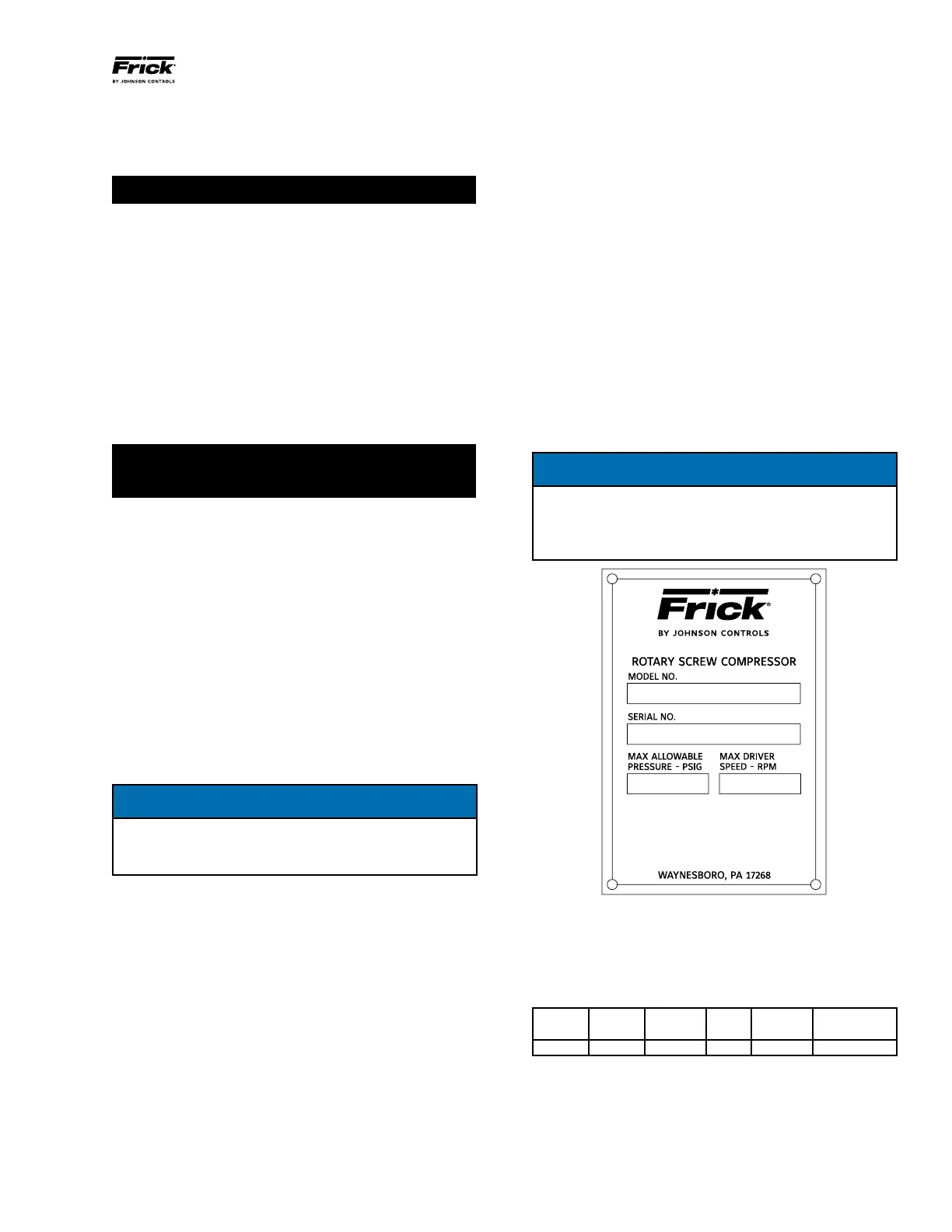
COMPRESSOR IDENTIFICATION
Each compressor has an identication data plate, containing
compressor model and serial number mounted on the
compressor body.
NOTICE
When inquiring about the compressor or unit, or
ordering repair parts, provide the MODEL, SERIAL, and
JOHNSON CONTROLS - FRICK SALES ORDER NUMBERS
from the data plate. See Figure 1.
Figure 1 - Identication Data Plate
Rotary screw compressor serial numbers are dened by the
following information:
EXAMPLE: 10240A90000015Z
GLOBAL ADDITIONAL
PLANT DECADE MONTH YEAR SEQ NO. REMARKS
1024 0 A 9 0000015 Z
Month: A = JAN, B = FEB, C = MAR, D = APR, E = MAY, F =
JUN, G = JUL, H = AUG, K = SEP, L = OCT, M = NOV, N = DEC.
Additional Remarks: R = Remanufactured; Z = Deviation
from Standard Conguration.
Geometrical swept volume table ...