070-450 IOM (NOV 13)
Page 17
XJF ROTARY SCREW COMPRESSOR
INSTALLATION
OIL FILTER(S)
Your package must be equipped with full-ow oil ltration.
Typical oil lter specication β
5
= 75 according to ISO 4572
is required to obtain the recommended oil cleanliness class
16/14/11 according to ISO 4406. Frick SuperFilters
™
can be
ordered separately.
OIL COOLING REQUIREMENTS
Compressor oil needs to be cooled to control the discharge
temperature, maintain proper oil viscosity and to preserve
the life of the oil. Normally the discharge temperature will
be in the 170° - 180°F range (see CoolWare
™
).
One application that typically requires higher discharge
temperatures (as high as 250°F) is natural gas gathering at
the wellhead
1
. Moisture is normally present in the gas and
it is imperative that the discharge temperature be at least
30°F higher than the discharge dew point temperature for
the gas. Run Coolware with the “Water Saturated” block
checked to get the discharge dew point temperature for
your application. Oil temperatures as high as 170°F can be
used to achieve the necessary discharge temperature to
prevent moisture from condensing in the oil separator.
1
Contact Johnson Controls–Frick for additional information
for natural gas compression - availability of bearings for
high temperature applications - standard bearings have
limitations per Coolware that must be observed.
The main oil injection line must have a regulating valve to
permit adjustment of the oil ow to maintain the desired
discharge temperature at all times.
The use of a three-way mixing valve is recommended to
keep the oil temperature in the normal range of 120° -
140°F. The valve will provide warm oil to the compressor
quickly, reducing the pressure drop caused by cold, viscous
oil. This ensures proper oil ow and temperature over the
full range of operating conditions.
ECONOMIZER - HIGH STAGE
The economizer option provides an increase in system capac-
ity and efciency by subcooling liquid from the condenser
through a heat exchanger or ash tank before it goes to the
evapora tor. The subcooling is provided by ashing liquid in
the economizer cooler to an intermediate pressure level.The
intermediate pressure is provided by a port located part way
down the compres sion process on the screw compressor.
As the screw compressor unloads, the economizer port will
drop in pressure level, eventually being fully open to suc-
tion. Because of this, an output from the microproces sor is
generally used to turn off the supply of ashing liquid on a
shell and coil or DX economizer when the capacity falls below
approximately 60%-70% (85%-90% slide valve position). This
is done to improve compressor operating efciency. Please
note however that shell and coil and DX economizers can be
used at low compressor capaciti es in cases where efcien-
cy is not as important as ensuring that the liquid supply is
subcooled. In such cases, the economi zer liquid solenoid can
be left open whenever the com pressor is running.
Due to the tendency of the port pressure to fall with de-
creasing compressor capacity, a back-pressure regulator
valve (BPR) is generally required on a Flash Economizer
System (Figure 6) in order to maintain some preset pressure
dif ference between the subcooled liquid in the ash vessel
and the evaporato rs. If the back-pressure regulator valve is
not used on a ash economizer, it is possible that no pressure
difference will exist to drive liquid from the ash vessel to the
evaporators, since the ash vessel will be at suction pressure.
In cases where wide swings in pressure are anticipated in
the ash econo mizer vessel, it may be necessary to add an
outlet pressure regulator to the ash vessel outlet to avoid
overpressurizing the economizer port, which could result
in motor overload. Example: A system feeding liquid to the
ash vessel in batches.
The recommended economizer systems are shown in Figures
4 – 7. Notice that in all systems there must be a strainer
and a check valve between the economizer vessel and the
economizer port on the compressor. The strainer prevents
dirt from passing into the compressor and the check valve
prevents oil from owing from the compressor unit to the
econo mizer vessel during shutdown.
CAUTION
Other than the isolation valve needed for strainer cleaning, it
is essential that the strainer be the last device in the
economizer line before the compres sor. The strainer must
be strong enough to handle the gas pulsations from the
compressor. Johnson Controls-Frick recommends an R/S
or Hansen strainer. Also, piston-type check valves are
recom mended for installation in the economizer line, as
opposed to disc-type check valves. The latter are more
prone to gas-pulsation-induced failure. The isolation and
check valves and strainer should be located as closely as
possible to the compressor, preferably within a few feet.
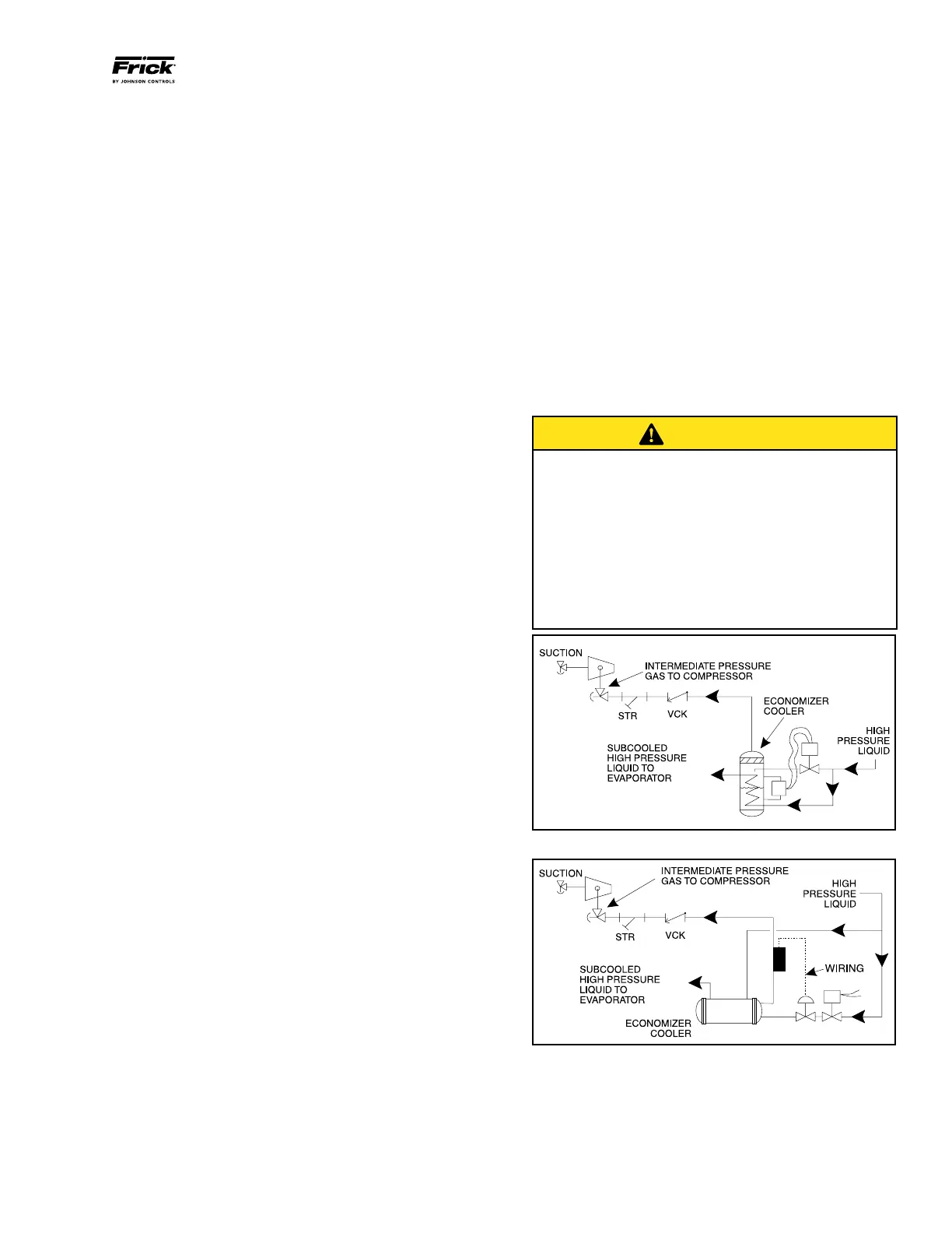
Figure 4 - Shell And Coil Economizer System
Figure 5 - Direct Expansion Economizer System
For refrigeration plants employing multiple compressors on
a common economizing vessel, regardless of economizer
type, each compressor must have a back-pressure regulat-
ing valve in order to balance the economizer load, or gas
ow, between compressors. The problem of balancing load
becomes most important when one or more compressors