58 PB
INSTALLATION
Wall Controller Installation 12 & 24k
25
Wall Controller Installation
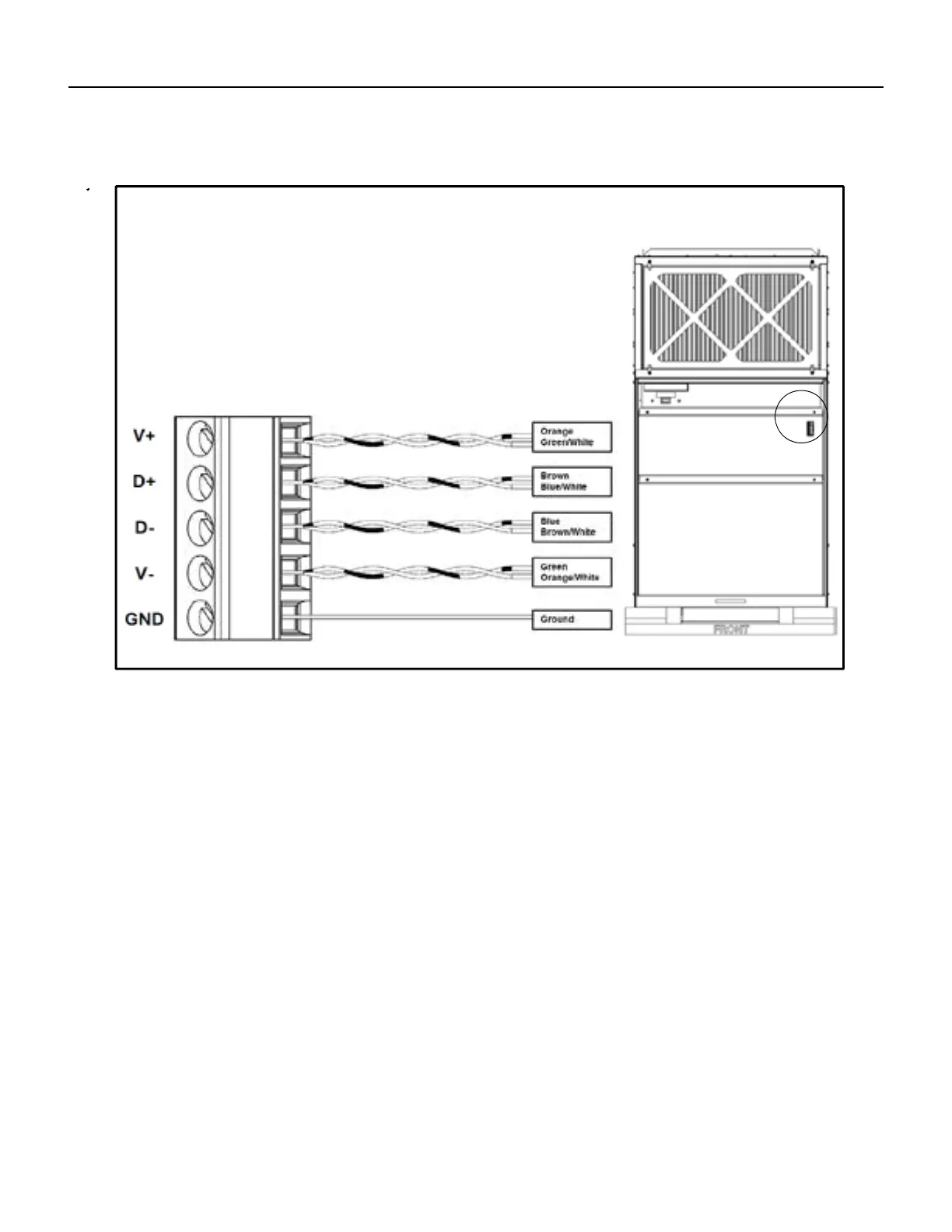
Wiring to the VRP Unit
A. Strip the wire ends to 9/16" (15 mm).
B. Insert the wire pairs into terminals as shown below.
C. Insert ground shield wire into ground terminal (marked with a
ground symbol).
D. Tighten the screws to secure the wires to the corresponding
terminals.
E. Pull the wires to check that they are securely affixed to the
terminal block.
26
Electrical Installation
Electrical Installation
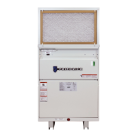
Remove and discard hole knock-out from the side
of the unit (Detail A)
Remove the Electrical Access Panel (Detail B) to
expose the Incoming Power Terminal Block
(Detail C, see below)
B
Ground L1 L2
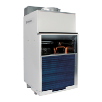
Insert all wires (Green, Black, Red) through the
punched out hole and fasten wires as follows:
Green to Ground
Black to L1
Red to L2
C
l
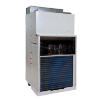
Remove and discard hole knock-out from
the side of the unit (Detail A)
Remove the electrical access panel to expose the incoming
Ppwer terminal block (Detail C, see below)
Insert all wires through the
punched out hole and fasten
wires as follows:
Ground
L1L2
FIGURE 417 (Wall Controller Installation)
 Loading...