60
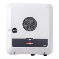
Display Power for the display comes from the AC grid voltage. The display can be available all day
long depending on the setting in the Setup menu.
Display area, display mode
Display area, setup mode
(*) Scroll bars
(**) Inverter no. = inverter DATCOM number,
USB connection - appears if a USB stick was connected,
storage symbol - appears briefly when set values are stored
Symbols for func-
tion key functions
The following symbols are shown on the display for function key assignment:
IMPORTANT! The inverter display is not a calibrated measuring instrument. Slight devia-
tion of a few percentage points from the utility company meter is intrinsic to the system. A
calibrated meter is required to make calculations for the utility company.
 Loading...