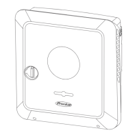
Attaching the Mounting Bracket
Safety
WARNING!
Danger due to residual voltage in capacitors.
This may result in an electric shock.
▶
Wait for the capacitors to discharge. The discharge time is five minutes.
CAUTION!
Danger due to dirt or water on the terminals and contacts of the inverter's con-
nection area.
This may result in damage to the inverter.
▶
When drilling, ensure that terminals and contacts in the connection area do
not become dirty or wet.
▶
The mounting bracket without a power stage set does not conform to the
protection class of the inverter as a whole, and therefore must not be in-
stalled without a power stage set.
▶
The mounting bracket should be protected from dirt and moisture during in-
stallation.
Note! Degree of protection IP 65 is only applicable if
-
the inverter is placed in the mounting bracket and permanently attached us-
ing screws,
-
the cover for the data communication area is permanently attached to the
inverter with screws.
Degree of protection IP 20 applies to the mounting bracket with no inverter and
the venting duct.
Selecting wall
plugs and screws
Important! Different fixings may be required to fit the mounting bracket depend-
ing on the type of underlying surface. Fixings are therefore not included in the
scope of supply of the inverter. The installer is responsible for selecting the right
type of fixing.
Recommended
screws
To install the inverter, the manufacturer recommends the use of steel or alumini-
um screws with a diameter of 6 - 8 mm.
Opening the in-
verter
WARNING!
Danger from inadequate ground conductor connection.
This can result in serious injury and damage to property.
▶
The housing screws provide a suitable ground conductor connection for
grounding the housing and must NOT be replaced by any other screws that
do not provide a reliable ground conductor connection.
11
EN
 Loading...