NOTE! If the inverter is installed in Australia or New Zealand (required standard:
AS4777.2:2020), the following applies:
-
Functional grounding isnot permitted
-
The inverter must not be used as part of a three-phase combination, as there
is no communication link between the inverters
General com-
ments regarding
solar modules
To enable suitable solar modules to be chosen and to use the inverter as effi-
ciently as possible, it is important to bear the following points in mind:
-
If insolation is constant and the temperature is falling, the open circuit
voltage of the solar modules will increase.
-
The temperature coefficients on the solar modules data sheet must be ob-
served
-
More exact values for dimensioning the solar modules can be provided by
suitable calculation programs, like the Fronius Solar.creator (creator.froni-
us.com).
NOTE!
Before connecting up the solar modules, check that the voltage for the solar
modules specified by the manufacturer corresponds to the actual measured
voltage.
The solar module manufacturer's safety instructions and regulations regarding
solar module grounding must be observed.
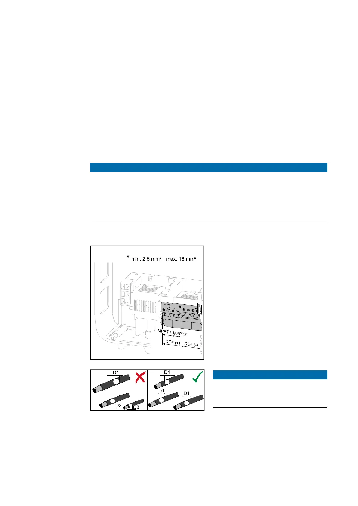
DC terminals Max. cross-section of each DC cable:
16 mm²
Min. cross-section of each DC cable:
2.5 mm²
The DC cables can be connected to
the DC terminals without ferrules.
NOTE!
To ensure effective strain relief of the
solar module strings, only use cables
with identical cross-sections.
IMPORTANT! When using ferrules for DC cables with a cross-section of 16 mm²,
the ferrules must be crimped with a right-angled cross-section.
The use of ferrules with insulating collars is only permitted up to a max. cable
cross-section of 10 mm².
22

 Loading...