Cable routing in
the DC area
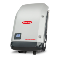
If DC cables are laid over the shaft of
the DC main switch or across the con-
nection block of the DC main switch,
they may be damaged when the invert-
er is swung in or they may even prevent
the inverter from being swung in.
IMPORTANT! Do not lay DC cables
over the shaft of the DC main switch
or across the connection block of the
DC main switch.
Multi MPP track-
er inverters -
Fronius Primo
3.0 - 8.2
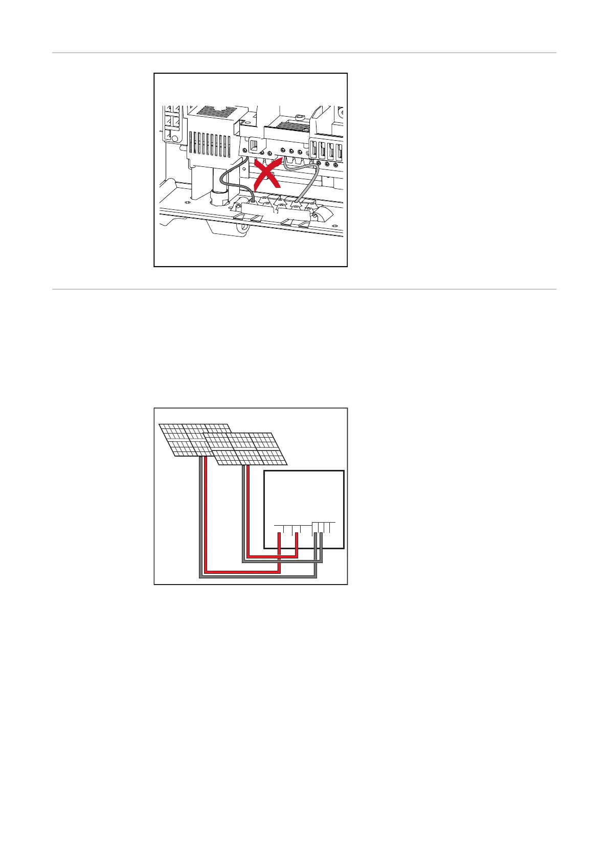
In the case of inverters with multiple MPP trackers, there are two independent
DC inputs (MPP trackers) available. These can be connected to an unequal num-
ber of solar modules.
There are two terminals for DC+ available per MPP tracker. In total there are four
terminals for DC-.
Connecting two to four strings in multiple MPP tracker mode:
DC-2
DC-
DC-1
Primo 3.0 - 5.0:
max. 12 A per MPPT
Primo 5.0 AUS - 8.2:
max. 18 A per MPPT
PV 1
PV 2
1 2
1 2
3 4
1 2
DC+1 DC+2
DC+1
DC+2
Connecting two solar module fields to an invert-
er with multiple MPP trackers
Divide the strings between the two
MPP tracker inputs (DC+1/DC+2). The
DC- terminals can be used however
you wish, as they are internally connec-
ted.
When starting for the first time, set
MPP TRACKER 2 to "ON" (this can also
be done later in the Basic menu).
26
 Loading...