10
Fig.8 Temperature sensor wiring diagram
(1)
(2)
X 7/3
X 7/5
(1) Charger
(2) Temperature sensor
X 7/3 (brown)
X 7/5 (blue)
Aquamatic/end of
charging option
External stop
option (pilot
contact)
Opening connection X 7/2 and X 7/5
interrupts charging.
(1) Charger
X 7/2 (brown)
X 7/5 (blue)
Temperature-
controlled char-
ging option
Used for batteries with fixed electrolytes (gel, sealant), or for batteries in use in extreme
temperatures. The charging voltage is adapted depending on the battery temperature to
achieve faster or more gentle charging.
Important! Connect temperature sensor to the correct poles and connect to the negative
pole on the battery.
(1) (2)
X 6/3
X 6/4
N
L
4 A
X 6/PE
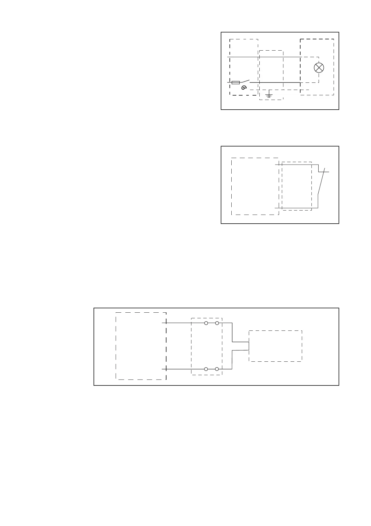
The Aquamatic option incorporates auto-
matic actuation of a solenoid valve to fill
the battery with water automatically.
The charging over option is used to
activate a signal lamp. When charging is
complete, the normally open contact
closes automatically.
(1) Charger
(2) Aquamatic/charging over
Fig.6 Aquamatic/charging over wiring diagram
Fig. 7 External stop wiring diagram
(1)
X 7/2
X 7/5