12
Error message Battery 100%
charged
Battery 80%
charged
Charging in
progress
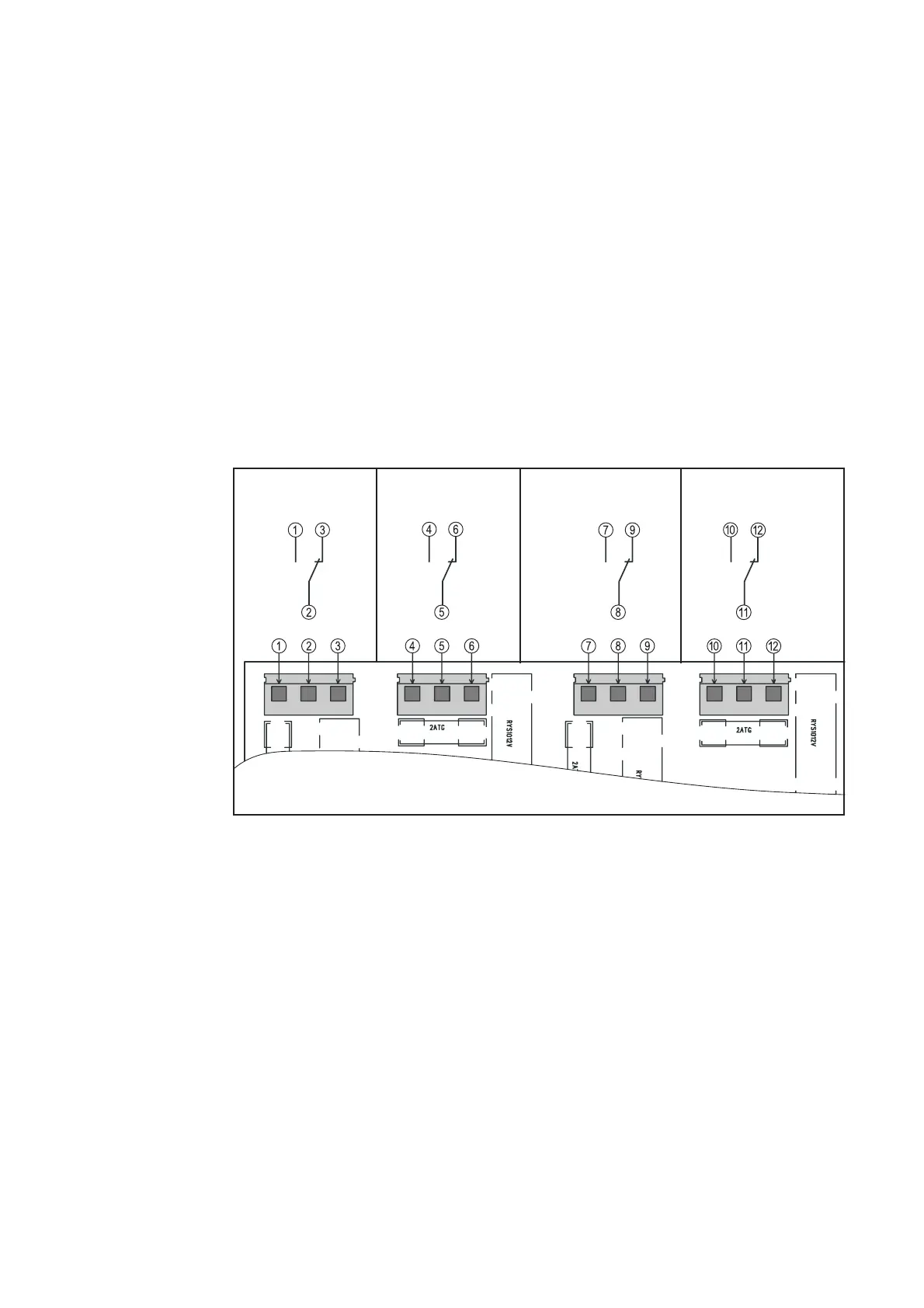
Fig. 11 Relay board: connecting the analysis lines
Max.: 250 V AC/DC, 2 A/cable
Relay board
option
The relay board is used to analyse
- basic information about the operating status of the charger
- the SOC of the connected battery
The analysis lines can be connected to a PLC or a process control system.
The connections for the analysis lines are like no-voltage change-over contacts with a
common root. The following information can be transferred:
- Battery charging/not charging
- Battery 80 % charged
- Battery fully charged
- Charger is working correctly/charger has output an error message
Connecting lines to the relay board
1. Disconnect charger from the mains
2. Disconnect the battery
3. Remove housing cover
4. On the relay board, connect the analysis lines to connections (1) to (12)
5. On the front of the housing (mains cable side), put the analysis line through the pre-
installed bushing (PG 11)
6. Fit housing cover